Back
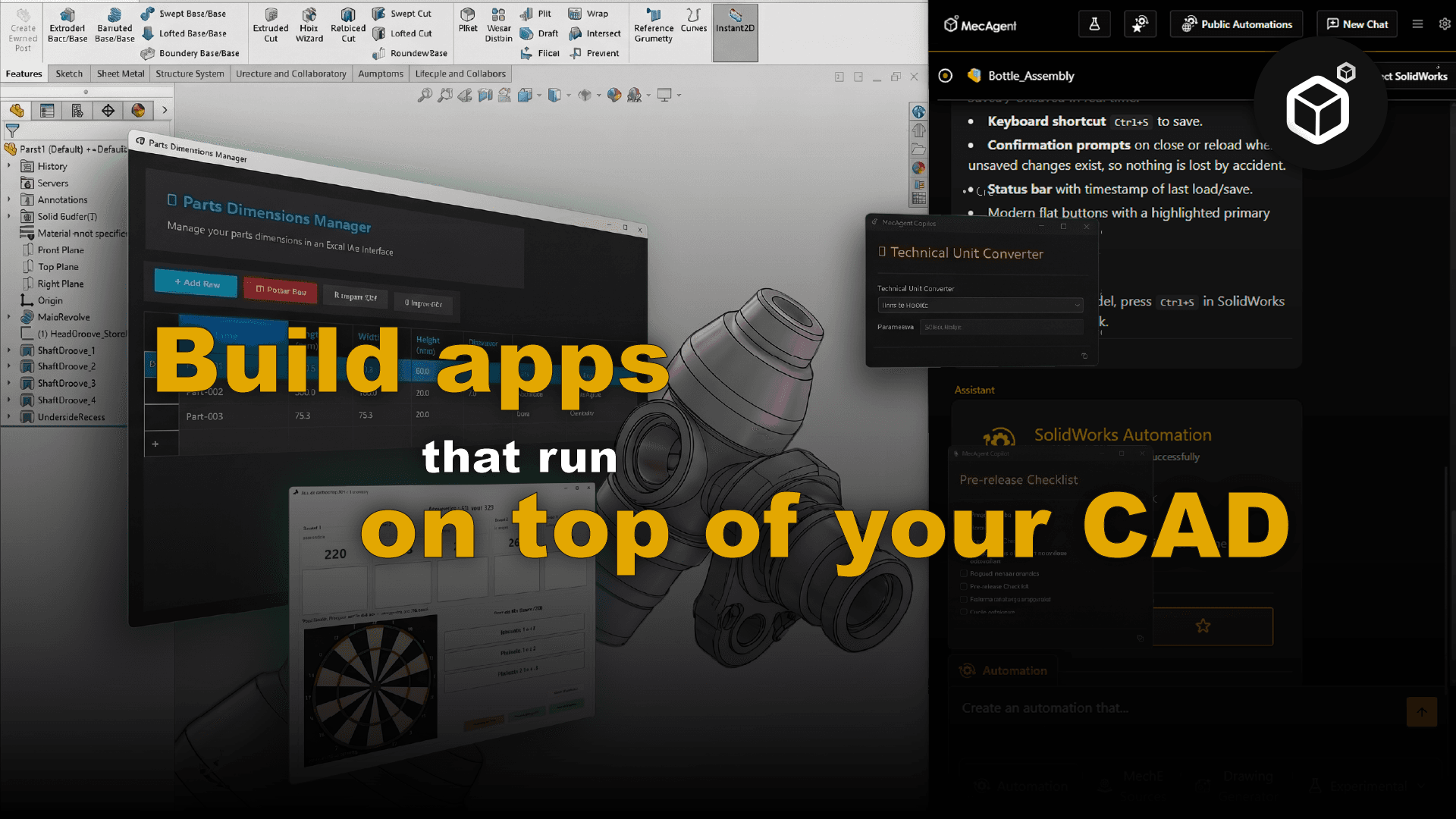
Text-to-Macro-to-CAD - The Future of Design
From natural language to intelligent CAD automation through AI-driven macro generation

1. The revolution of Text-to-CAD
Historically, the creation of Computer-Aided Design (CAD) models required considerable expertise, months of training on complex software, and numerous time-consuming iterations.
Today, Text-to-CAD makes it possible to convert clear natural language descriptions into editable 2D drawings or 3D CAD models. By writing a precise request including dimensions, materials, and constraints, for example, “a steel bracket 150 mm x 80 mm with four M8 bolt holes,” AI is able to generate usable geometry in a matter of seconds. These models can be exported in standard industrial formats such as STEP, STL, DXF, or DWG, ready to be imported into CAD software or sent for 3D printing.
However, it is important to be precise about what this technology covers. In its most basic form, Text-to-CAD generates static geometries that are often not very parametric and are difficult to edit. Quality and accuracy quickly drop as parts become more complex. A geometrically generated model is not necessarily functionally correct: tolerances, mechanical strength, and manufacturability remain key points that require validation by an engineer.
Nevertheless, this technology produces two real impacts:
Partial democratization of engineering: non-specialists can initiate a design from a textual description, accelerating early iterations.
An acceleration of the development cycle: for simple and well-defined parts, the time required to generate a first model drops from several hours to a few minutes.
2. The essential role of macros in CAD software
To understand the next step in this evolution, it is necessary to look at the native automation tools in software such as SOLIDWORKS or Inventor.
In these environments, macros are scripts that automatically execute a series of operations by directly calling the software API. Concretely, a macro records or codes a sequence of actions menu selections, value inputs, tool selections to replay them in a reproducible way.
A macro can be created in two ways:
By recording: the software automatically captures the sequence of actions performed by the user in the interface.
By programming: the macro is manually coded in a dedicated editor, usually in Visual Basic for Applications (VBA) or C#.
These macros, saved in formats such as .swp or .swb for SOLIDWORKS, are extremely powerful for eliminating repetitive tasks. Their main limitation remains the technical barrier: fully exploiting their potential requires programming skills, which limits their adoption among designers as a whole.
3. Convergence: Text-to-Macro-to-CAD with MecAgent
This is where the real innovation brought by tools such as MecAgent lies. Rather than generating a static 3D file as in classical Text-to-CAD, MecAgent acts as an AI copilot integrated directly into CAD software SOLIDWORKS or Inventor and generates macros on the fly from textual descriptions.
This point is fundamental and represents a major qualitative leap compared to previous approaches. By going through macro generation, MecAgent uses the native tools of the software its own modeling algorithms, its geometric constraint solvers, its dimensioning tools which ensures that the generated parts respect the software conventions, parametric constraints, and dimensional accuracy expected in an industrial context. The resulting geometry is not approximated: it is built by the software itself, from instructions generated by AI.
In practice, the engineer describes in natural language what they need: dimensions, materials, part type, functional constraints and MecAgent generates the corresponding macro that drives SOLIDWORKS or Inventor to create the part with the precision inherent to these environments.
Example of prompts and CAD models parts and assemblies to create:
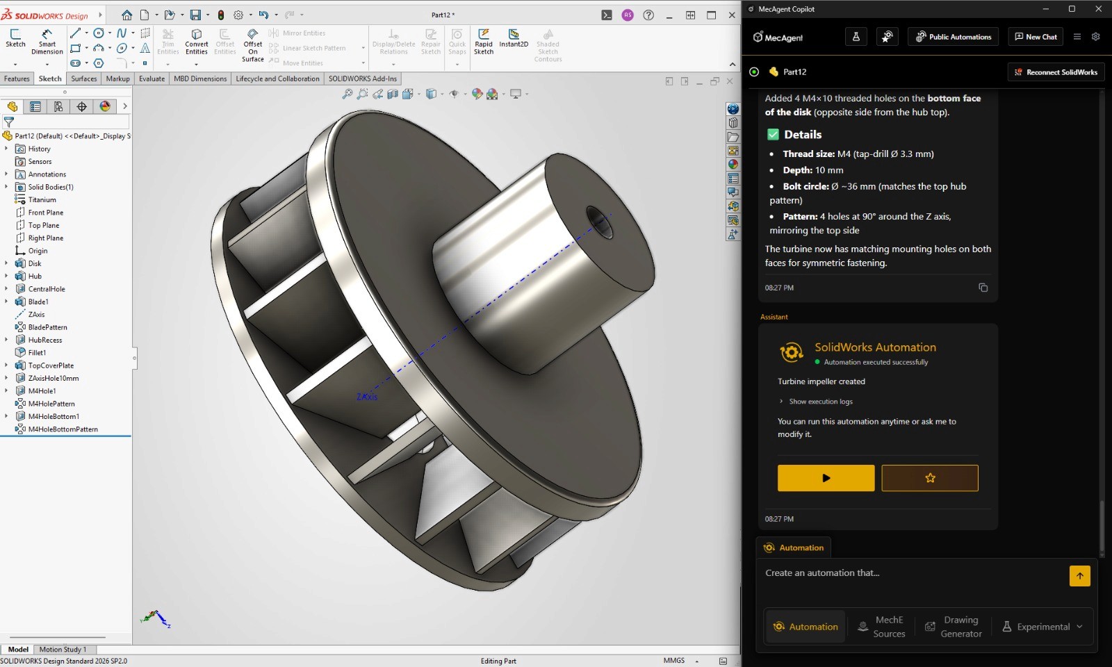
Turbine :
Create a single-piece turbine impeller as a CAD model.
Important constraint: this must be one continuous solid part, not an assembly. Do not create separate components.
Step 1: Create a central cylindrical hub with a diameter of 42 mm and a height of 38 mm.
Step 2: Add a central through-hole along the rotation axis. The hole should have a diameter of 14 mm.
Step 3: Around the hub, create a circular base disk with an outer diameter of 120 mm and a thickness of 8 mm. The disk and hub must be fused into one continuous solid body.
Step 4: Create 14 curved turbine blades arranged evenly around the hub. Each blade should start near the hub at a radius of 24 mm and extend outward to a radius of 58 mm.
Step 5: Each blade should be swept backward in the direction of rotation, with approximately 35 degrees of curvature from root to tip.
Step 6: Each blade should have a thickness of 3 mm at the root and taper to 1.5 mm at the tip.
Step 7: Each blade should rise from the base disk with a height of 28 mm near the hub and gradually reduce to 18 mm near the outer tip.
Step 8: Blend each blade smoothly into the hub and base disk using large root fillets of 3 mm.
Step 9: Add a shallow circular recess on the top face of the hub, 30 mm in diameter and 2 mm deep.
Step 10: Add a 2 mm chamfer around the central through-hole on both sides.
Step 11: Add a 1.5 mm fillet around the outer perimeter of the disk.
Step 12: Apply a brushed titanium material to the entire part.
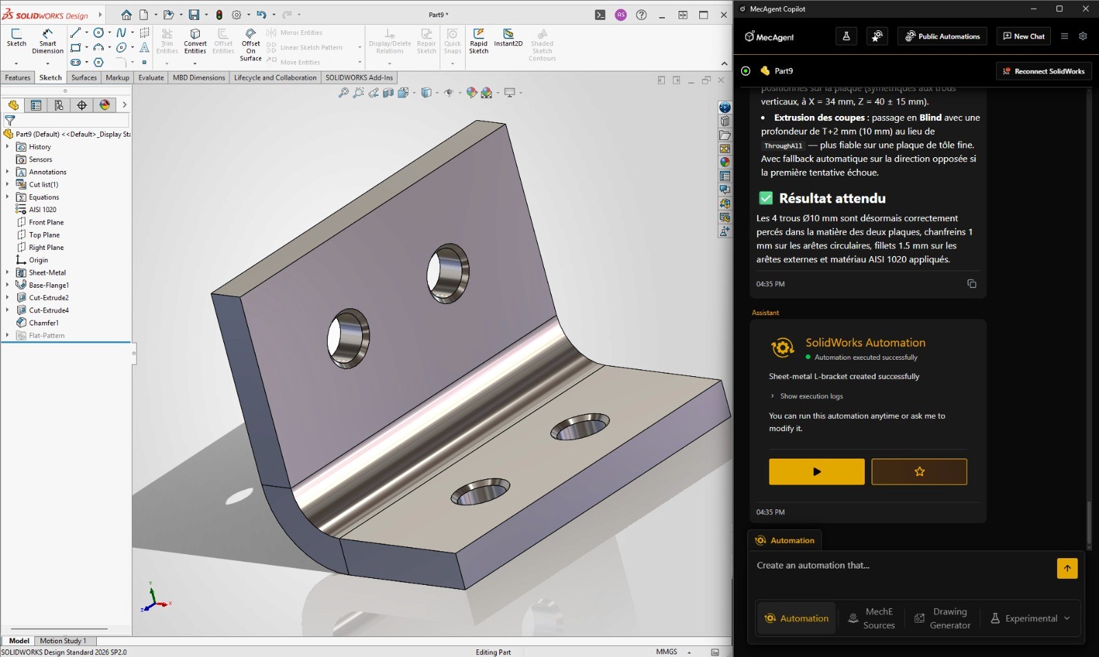
L Bracket :
Create a single-piece mechanical mounting bracket as a CAD model.
Important constraint: this must be one continuous solid part, not an assembly. Do not create separate components.
Step 1: Create an L-shaped bracket made from two perpendicular plates.
Step 2: The vertical plate should be 80 mm wide, 60 mm tall, and 8 mm thick.
Step 3: The horizontal plate should be 80 mm wide, 50 mm deep, and 8 mm thick.
Step 4: Fuse both plates into one continuous body.
Step 5: Add an internal reinforcement fillet at the corner between the two plates with a radius of 10 mm.
Step 6: Add two through-holes on the vertical plate. Each hole should be 10 mm in diameter. Position them centered horizontally and spaced 30 mm apart vertically.
Step 7: Add two through-holes on the horizontal plate. Each hole should be 10 mm in diameter. Position them centered left-to-right and spaced 30 mm apart in depth.
Step 8: Add 1 mm chamfers around all hole edges.
Step 9: Add 1.5 mm fillets on all external edges.
Step 10: Apply a machined steel material to the entire part.
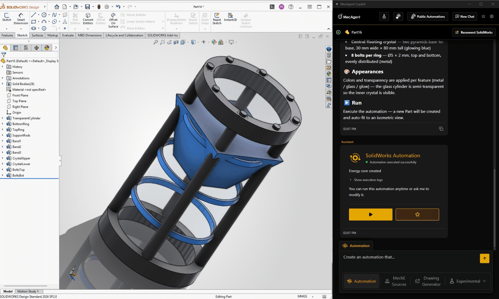
Sci-fi energy core cylinder
Create a sci-fi energy core cylinder as a CAD model.
Step 1: Create a central transparent cylinder with a diameter of 60 mm and a height of 140 mm.
Step 2: Add a top metal ring around the cylinder. The ring should have an outer diameter of 76 mm, an inner diameter of 60 mm, and a height of 12 mm.
Step 3: Add a bottom metal ring with the same dimensions as the top ring.
Step 4: Create four vertical support rods evenly spaced around the transparent cylinder. Each rod should have a diameter of 8 mm and run from the bottom ring to the top ring.
Step 5: Add three thin glowing horizontal bands around the transparent cylinder. Place them at heights of 35 mm, 70 mm, and 105 mm. Each band should be 4 mm thick.
Step 6: Inside the transparent cylinder, create a floating central crystal shape. The crystal should be made from two pyramids joined base-to-base, with a total height of 80 mm and a maximum width of 30 mm.
Step 7: Add small circular bolts on the top and bottom rings. Use 8 bolts per ring, evenly distributed.
Step 8: Apply dark brushed metal material to the rings and rods. Apply transparent glass material to the cylinder. Apply glowing blue material to the inner crystal and horizontal bands.
Overall, the capabilities of this copilot cover several dimensions of the workflow:
Precise mechanical part generation: from a textual description including dimensions, materials, etc., MecAgent produces parts directly usable in design, leveraging the software’s native tools to ensure accuracy.
Global automation: bulk export management, property updates, material assignment, constraint application, standards checking.
Automated manufacturing drawings: automatic technical drawings including views, tables, and annotations, generated from existing CAD models.
In conclusion, the differentiating value of this approach does not lie in generating an approximate geometric shape, but in using AI to intelligently drive the tools of professional CAD software. MecAgent does not replace SOLIDWORKS or Inventor it orchestrates them, taking over repetitive configuration and modeling tasks so engineers can focus on what truly matters: innovation, technical judgment, and solving complex problems.

MecAgent Inc.

Other articles you might like
Learn how to increase your productivity with calendars