Back
Claude Opus 4.8 for CAD
Advancing Mechanical Engineering Automation with MecAgent Copilot 1.2

Claude Opus 4.8 for CAD
Advancing Mechanical Engineering with Claude Opus 4.8 and MecAgent Copilot 1.2
Introduction
The evolution of large language models is no longer limited to text generation. The latest generation of AI models can now assist engineers with script development, CAD task automation, technical data analysis, and the validation of parametric models.
This is where Anthropic's Claude Opus 4.8 comes into play. Anthropic provides the foundational AI model—a powerful technological engine upon which startups can build their own specialized solutions. By integrating agentic systems and fine-tuning the model on domain-specific engineering data, these companies are able to apply this raw intelligence to the fields of 3D design and computer-aided design (CAD).
For a solution such as MecAgent, this synergy enables intelligent, autonomous automation to be deployed directly within industry-leading CAD platforms such as SOLIDWORKS and Autodesk Inventor, while ensuring that engineers retain full human oversight and control throughout the design process.
Claude Opus 4.8
Unlike approaches that focus primarily on maximizing raw performance, Claude Opus 4.8 places a strong emphasis on behavioral robustness and the explicit management of uncertainty.
In practice, the model is more likely to acknowledge its limitations when sufficient information is unavailable rather than generate a potentially incorrect response. This approach helps reduce the risk of AI hallucinations—an especially important consideration in industrial environments, where design or calculation errors can have significant consequences.
This philosophy also extends to agentic environments such as Claude Code, where the model generally favors cautious, verifiable strategies over aggressive modifications or actions that are difficult to trace and validate.
Key Published Performance Metrics
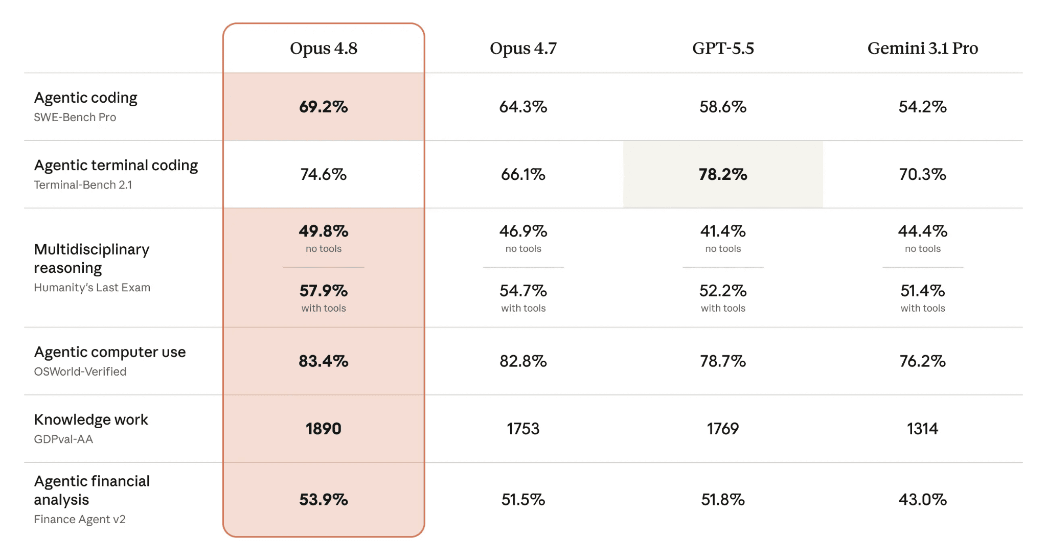
These results confirm Claude Opus 4.8's strong specialization in software development, automation, and technical assistance. For a solution such as MecAgent, the primary benefits lie in macro generation, parametric model analysis, and the automation of engineering workflows.
Benchmark Test / Model | Opus 4.6 (Score /20) | Opus 4.7 (Score /20) | Opus 4.8 (Score /20) |
OpenSCAD Nema 17 | 12.5 | 18.0 | 19.5 |
OpenSCAD V8 engine Block | 9.5 | 15.0 | 17.0 |
Average Response Time | 2 min 20 s | 5 min 35 s | 6 min 45 s |
Total Score (/40) | 22 | 33 | 36.5 |
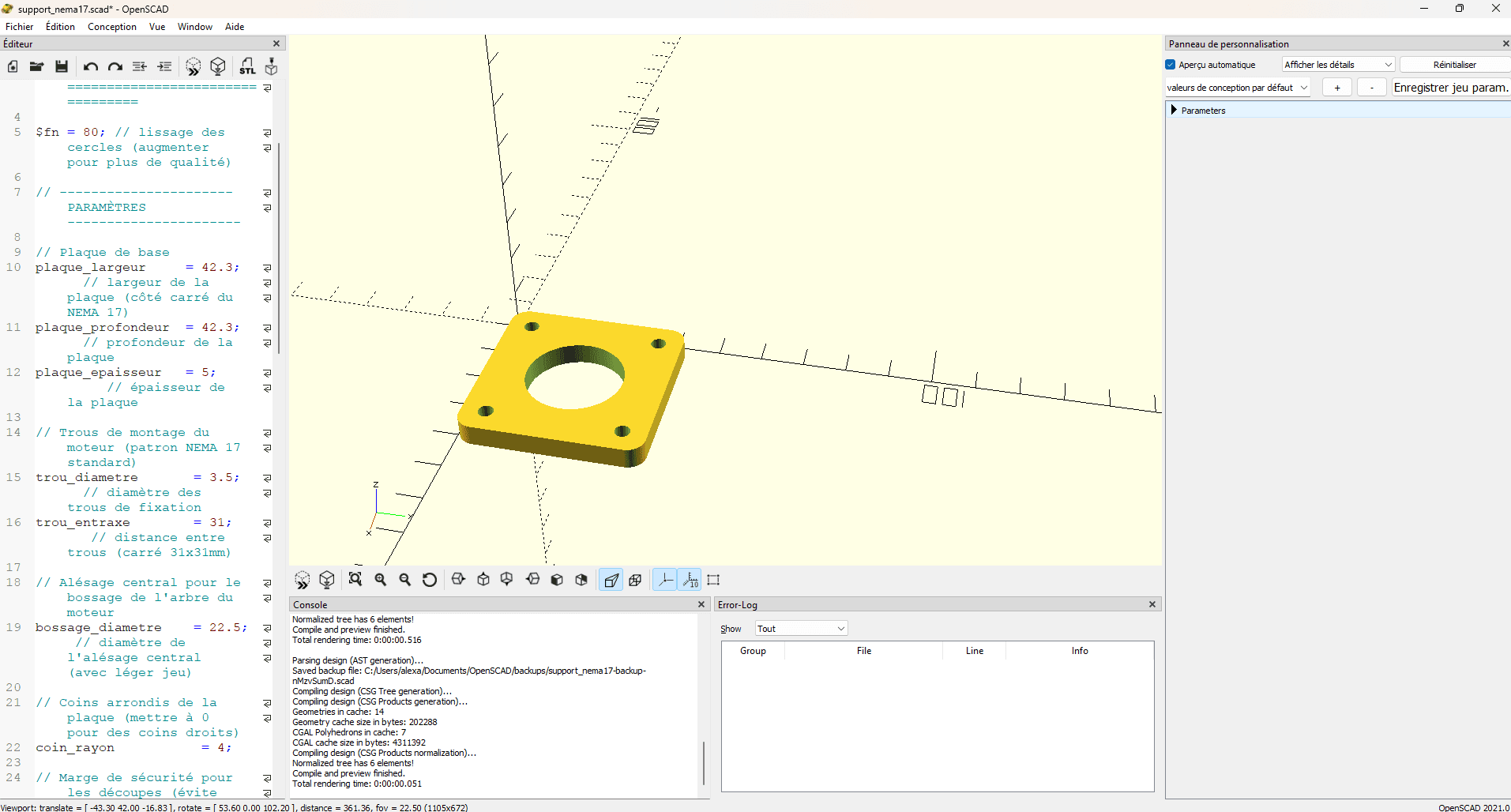
Opus 4.6: The model performs very well in terms of code quality, producing error-free code and a clean visual result on the first execution. However, the robustness test exposes a lack of geometric reasoning: the holes are positioned using fixed coordinates. As a result, changing the size of the plate breaks the assembly, limiting the value of a parametric modeling environment such as OpenSCAD.
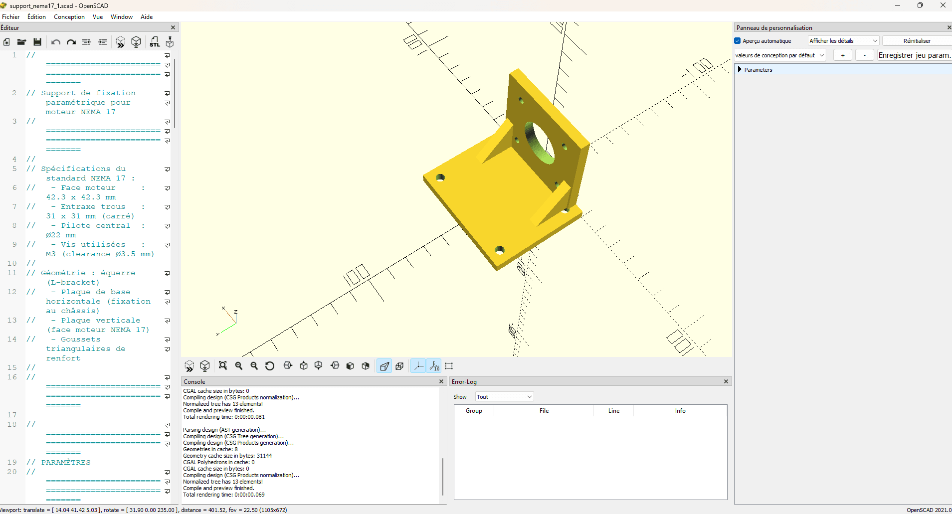
Opus 4.7: Although the model is slightly slower at generating code, the quality of the engineering output is significantly higher. Whereas Opus 4.6 produced rigid and brittle code that required manual intervention, Opus 4.7 incorporates native geometric reasoning, making the resulting model genuinely parametric, robust, and reusable.
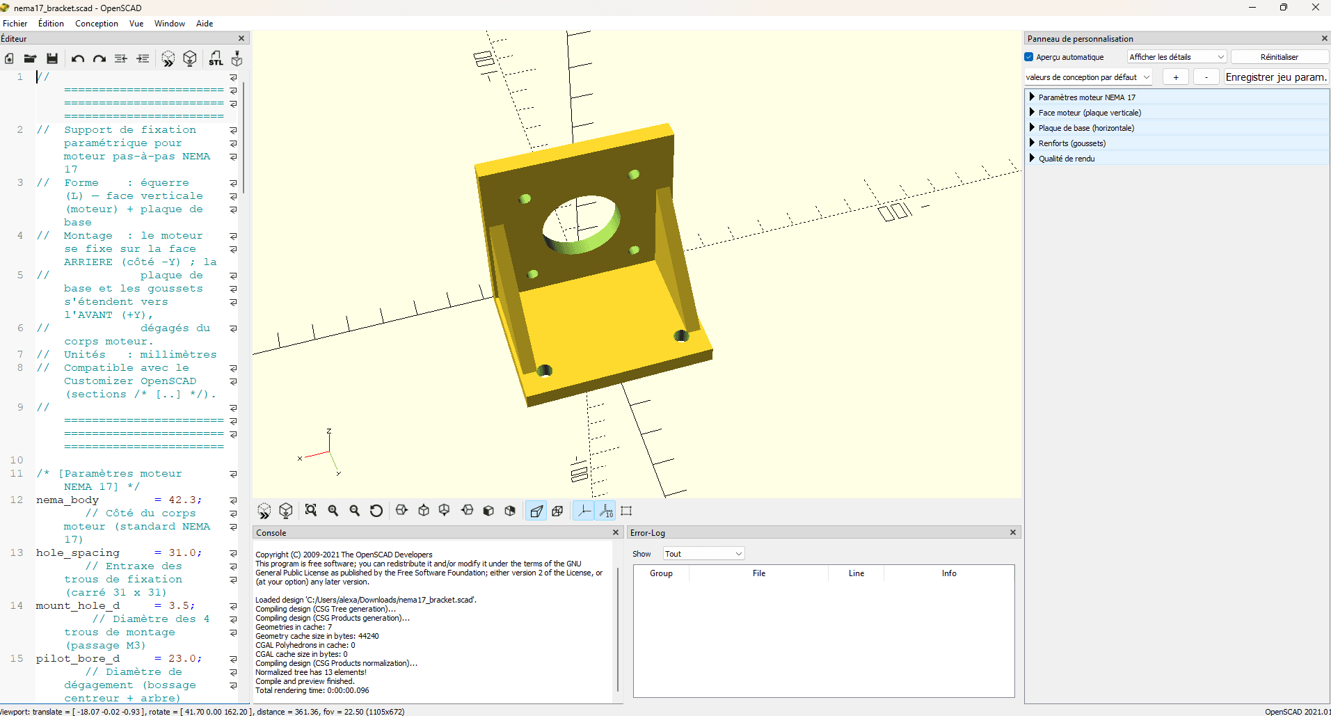
Opus 4.8: If the leap from Opus 4.6 to 4.7 was primarily about structural reliability, the advancement from 4.7 to 4.8 is largely about user experience. By natively supporting OpenSCAD's Customizer functionality, Opus 4.8 goes beyond simply generating code—it delivers a ready-to-use user interface. The additional generation time is the trade-off for a more sophisticated approach to usability and the overall end-user experience.
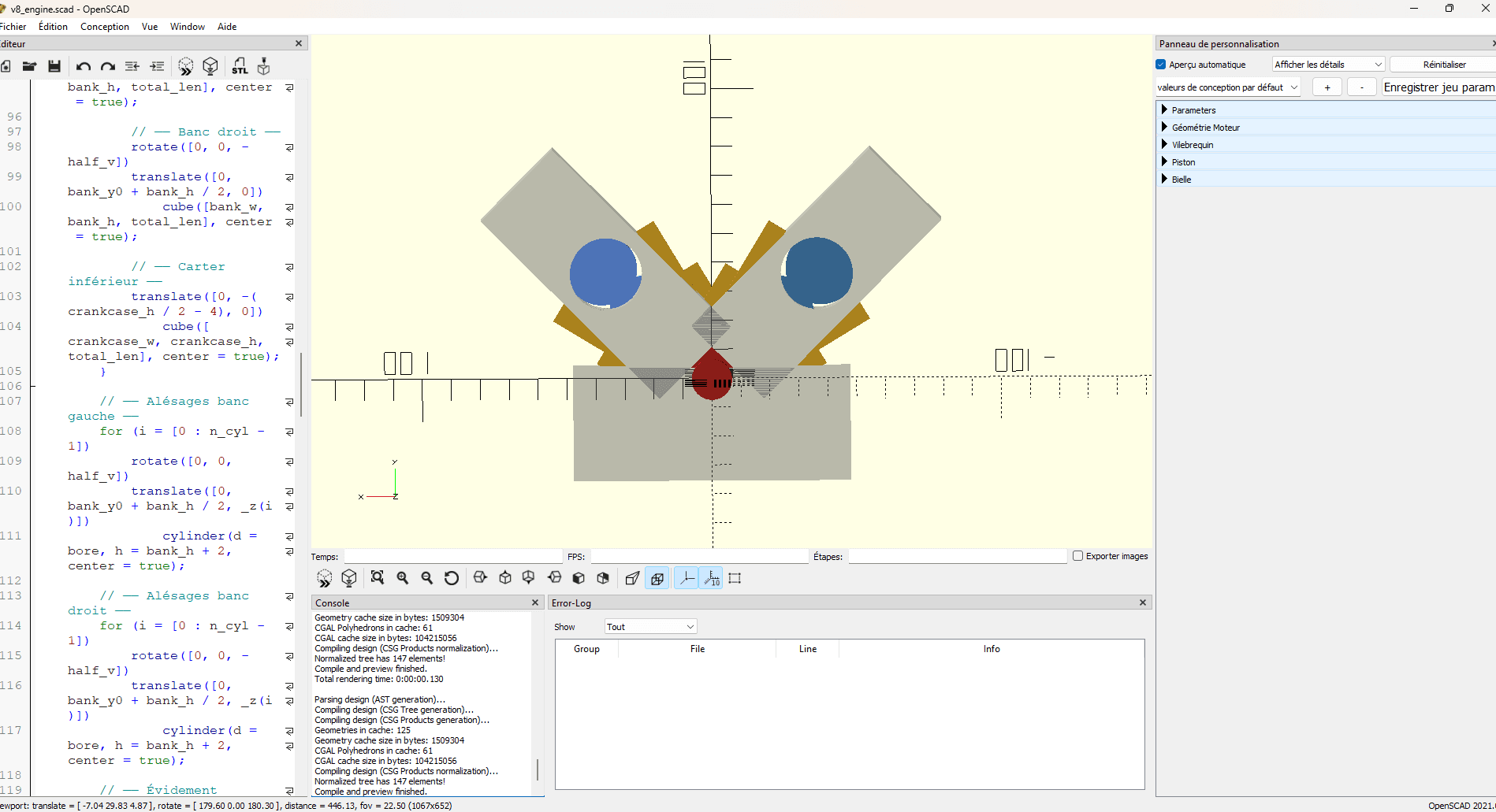
Opus 4.6: While the model is impressive at first glance for its ability to generate a complex structure, its limitations become apparent as soon as rigorous mechanical validation is required. Where we expected a realistic kinematic simulation, we instead obtained a visual mock-up: the code compiles successfully, but the geometry fails to comply with the laws of physics. The pistons extend beyond their cylinders, and the connecting rods lose their mechanical constraints.
From an engineering perspective, the conclusion is clear: Opus 4.6 produces syntactically correct code but mechanically incorrect semantics. It excels at building the framework of a program, yet it still falls short of accurately simulating the internal behavior of a mechanical system. As such, it provides an excellent starting point for developers, but it still requires substantial manual refinement before it can be considered a viable engineering design tool.
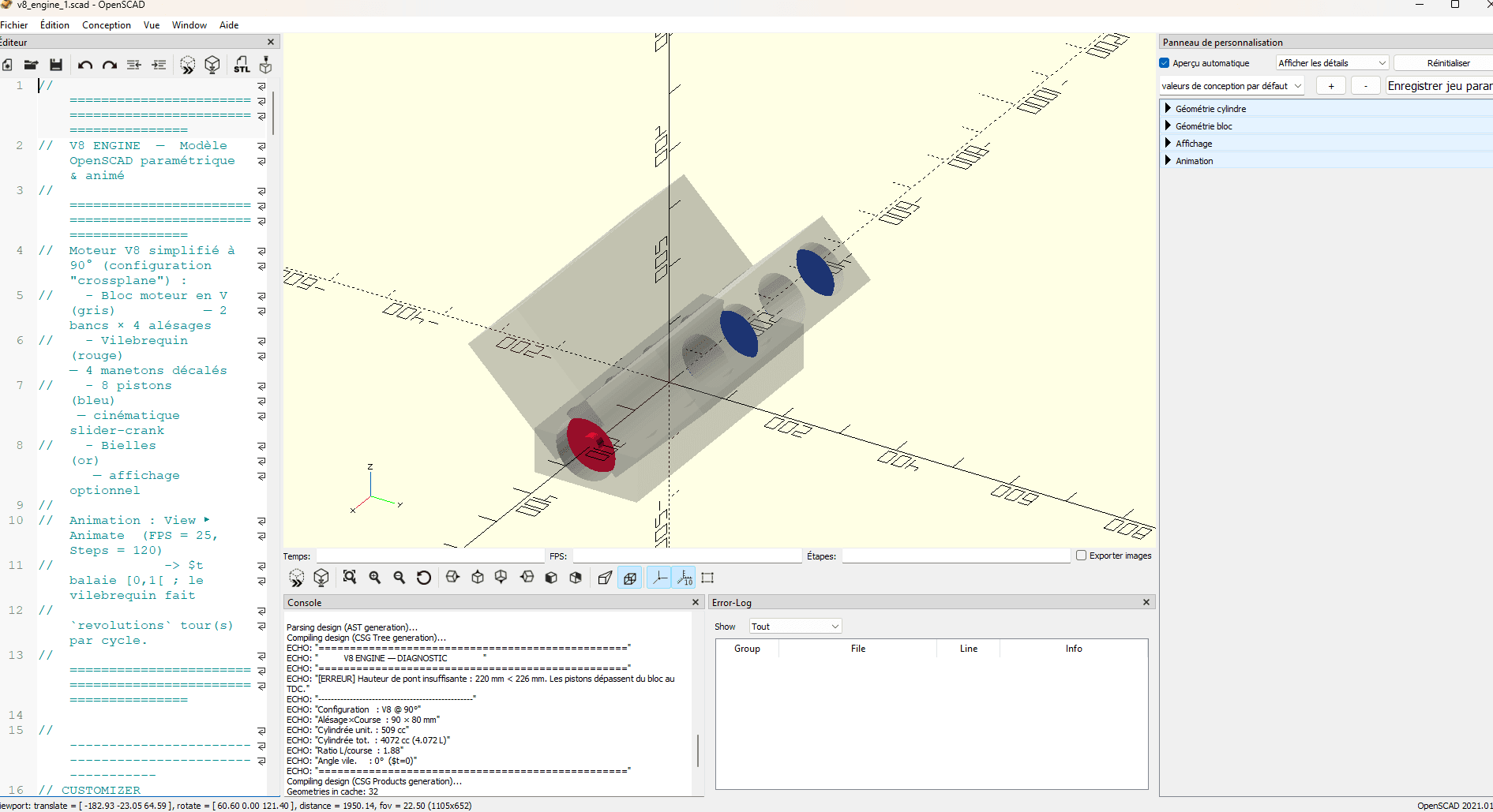
Opus 4.7: If model 4.6 merely displayed incorrect geometry, model 4.7 introduces a revolution in our methodology: self-validation. By integrating a safety_check module, the AI no longer simply generates shapes; it simulates an engineering verification process. Granted, the generated engine still has a bridge height error (the pistons extend beyond the block), but the AI explicitly informs us of this issue in the OpenSCAD console.
We have moved from a "shape generator" to a "design assistant capable of self-criticism." It is this qualitative leap from blind generation to an awareness of physical constraints that makes model 4.7 incomparably more robust and professional than its predecessor.
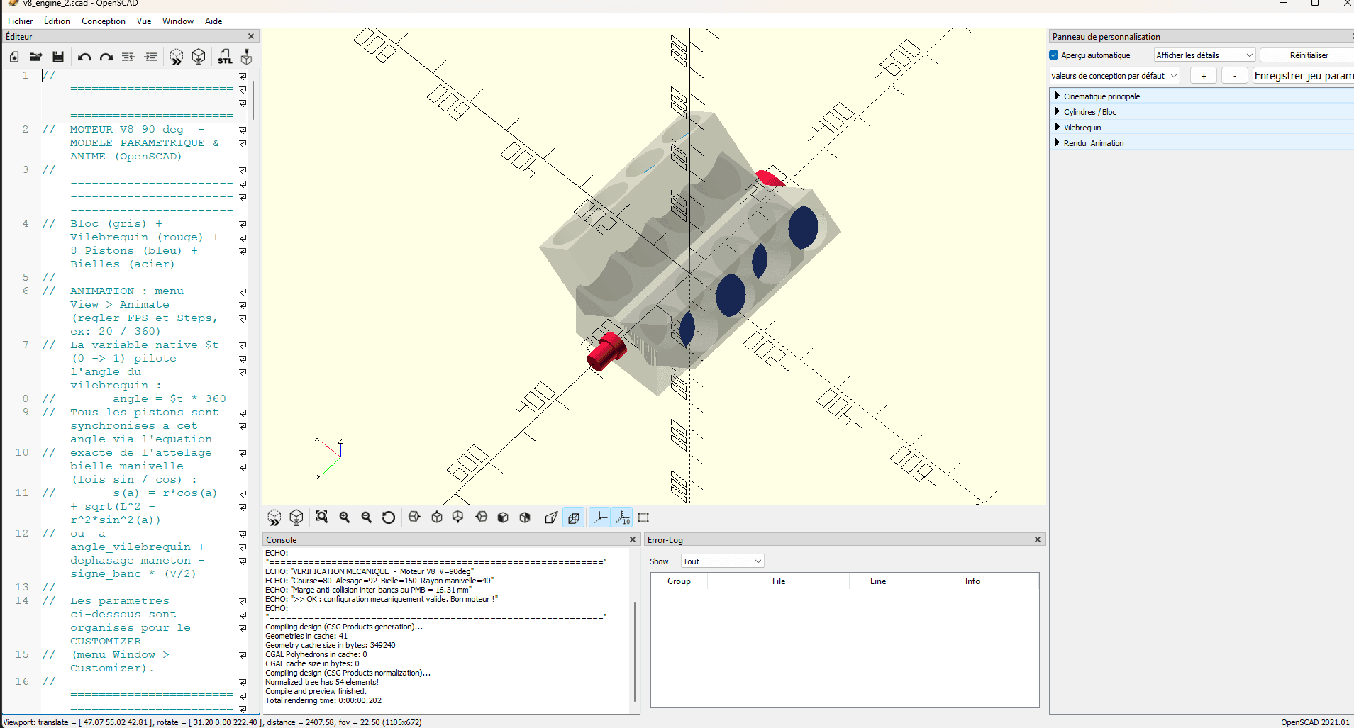
Opus 4.8: If model 4.7 introduced innovation through self-diagnosis, model 4.8 takes a decisive step forward: self-adaptive design. Thanks to dynamic derived variables, the AI no longer merely reports errors; it prevents them by calibrating the engine geometry itself. We therefore move from an assistant that can criticize its own work to a true design engineer capable of ensuring the structural validity of its design.
However, we must remain realistic: this qualitative leap toward geometric self-correction does not make AI a physical authority. Model 4.8 augments the engineer by automating tedious calculations, but it does not replace them. It produces an optimized proposal that remains a software simulation: only real-world experimentation or finite element analysis (FEA) can validate the strength and viability of the project. The AI proposes; the engineer decides.
Claude Opus 4.8 in Mechanical Engineering and 3D
One of the most promising areas for AI assistants in engineering is the generation of geometries from code. Claude Opus 4.8 is capable of producing code designed to create three-dimensional objects through libraries such as Three.js, OpenSCAD, or certain scriptable CAD environments. This capability makes it possible to generate simple parametric shapes, basic assemblies, or geometric automation scripts.
However, it is important to emphasize that the spatial reasoning capabilities of large language models remain limited today. Recent academic research shows that general-purpose models still face challenges when reconstructing or imagining complex geometries that require advanced spatial understanding.
Consequently:
Geometry Type | Level of Support |
Simple parametric parts | High |
Standard mechanical parts | High |
Simple assemblies | High |
Complex multi-body geometries | Medium |
Advanced surfaces and organic shapes | Limited |
Geometries requiring strong spatial reasoning | Limited |
The main value of the model still lies in accelerating pre-design work (calculations and project preparation) rather than in the autonomous generation of complex CAD models. Mesh model generation is also slightly improved with this new model.
Claude Opus 4.8 + MecAgent Copilot 1.2
1. CAD Macro Generation
For a copilot such as MecAgent, one of the major benefits of Claude Opus 4.8 lies in its ability to generate technical scripts:
SolidWorks macros;
Inventor macros;
3D space comprehension;
Generation of increasingly complex parametric parts and assemblies.
The model is particularly effective at understanding existing codebases, suggesting corrections, and documenting the modifications made. Claude 4.8 provides a more robust foundation for the agentic system that enables macro generation directly within CAD software. It therefore improves both the speed at which macro code is generated and its overall relevance.
The objective is not to replace the engineer, but to accelerate repetitive, low-value-added CAD tasks, allowing more time to be dedicated to engineering expertise and high-value design decisions.
2. The Four Pillars of AI Applied to CAD
CAD Script Generation and Maintenance
AI streamlines the daily workflow of designers by taking over repetitive automation tasks. It can instantly generate design macros and ensure their maintenance, allowing engineers to move away from writing code and focus more on innovation.
Text-Based Parametric CAD Model Generation (Text-to-CAD)
The creation of 3D models is entering a new era with the emergence of the Text-to-CAD concept. By relying on a true CAD Copilot, users can describe their requirements using natural language. The AI then applies a Text-to-Macro-to-CAD approach: it translates the textual description into macros directly interpretable by CAD software, generating a complete, dynamic, and fully editable parametric 3D model.
From 3D to 2D: AI-Assisted Parametric Drawing Creation
AI integration also provides significant value in the creation and management of engineering drawings. Current vision models are capable of accurately identifying the different dimensions within a 2D drawing. This technology provides a much stronger spatial understanding for automatically positioning views within the 2D environment. Furthermore, it greatly simplifies the selection of geometric elements, enabling AI to interact with drawings and modify dimensions in a much smoother and more intuitive way.
AI-Assisted Mechanical Engineering Support
Beyond pure 3D geometry generation, AI is now positioning itself as a genuine engineering resource. Through the specific retraining of the base model within the MecAgent ecosystem, technical teams gain access to a specialized agent capable of centralizing almost all of the company's engineering knowledge resources.
This advanced technical assistant is capable of:
Capability | Engineering Application |
Explain and Document | Clarifying complex design logic and rigorously documenting modeling decisions to ensure full traceability. |
Generate and Automate | Creating engineering rules and guidelines for parametric design processes. |
Support and Validate | Actively assisting critical design reviews and supporting early-stage validation of physical concepts. |
Optimize Sourcing | Facilitating the search for and selection of standard industrial components perfectly suited to technical requirements. |
The primary objective is to support engineers from the earliest pre-design stages, from the initial structuring of the design requirements specification (DRS) through to the first preliminary engineering calculations. By providing an AI capable of delivering technically rigorous, properly sourced results and documentation, MecAgent reduces the risk of hallucinations. This level of reliability is essential to ensure strict compliance with design requirements and to eliminate design errors before entering advanced calculation phases or prototyping.
3. Benchmark Opus 4.8 + MecAgent 1.2
Simple Macro: Batch Conversion
Criterion | Score | What to Evaluate |
API Integration | 3.3/5 | The macro fully leverages native API commands (OpenDoc6, InsertConvertToSheetMetal2). It even includes a fallback mechanism using the previous API method in case of failure. |
Code Robustness | 4.3/5 | Industrial-level quality. Critical sections (I/O, interface, loops) include try/catch handling, along with essential use of the finally block to guarantee the closure of open documents (CloseDoc), preventing unnecessary RAM usage. |
CAD Logic | 3.1/5 | The AI implements a highly effective algorithmic approach to automate design intent: calculating thickness through the bounding box and selecting the supporting face based on the maximum area of planar surfaces. |
Documentation | 4.1/5 | Beyond standard textual comments, the macro integrates a complete telemetry system in the console ([START], [INFO], [SUCCESS]) that enables real-time monitoring of the process state and instant debugging of files. |
The batch conversion macro produced goes beyond simple "routine automation." It demonstrates a genuine understanding of adaptive geometric analysis.
Strength: The AI understood that for a batch-processing workflow to be viable across an entire directory, it cannot rely on fixed values. Instead of imposing a default thickness, the script dynamically calculates the body bounding box (GetBodyBox) to determine the sheet metal thickness, then scans the feature tree to automatically select the largest planar face as a reference. This is what allows the workflow to run autonomously and transparently for the user.
Area for Improvement: To achieve a perfect industrial-grade score, the thickness detection method would need to be made more reliable. The assumption that the smallest bounding-box dimension corresponds to sheet thickness works well for flat blanks, but it will fail on complex parts that already include large bends or flanges developed along three axes (which can distort the overall bounding box). A local analysis based on the distance between two opposite parallel faces would be essential to secure the processing of geometrically complex parts.
Complex Macro: Assembly Generation (Text-to-CAD)
For this test, we pushed the Opus 4.8 + MecAgent combination to its limits: generating a fully functional water bottle assembly from start to finish (body, cap, and assembly constraints).
Required Effort: Approximately 20 iterative prompts and 2 hours of guidance were required to refine the geometric heuristics and achieve a production-ready result without collisions.
Criterion | Score | What to Evaluate / Results |
API Integration | 4.5/5 | Does the macro use native API commands (e.g., swApp, Part.FeatureManager) or is it generic and ineffective code? Excellent use of native classes (SldWorks, IModelDoc2, FeatureManager). The code does not rely on generic operations: it precisely manipulates IEntity, IFace2, and IEdge objects from the SolidWorks API. |
Code Robustness | 4.2/5 | Error handling (try/catch), variable cleanup, and preconditions (checking whether a part is open). Very good error management through systematic try/catch blocks. The code verifies file availability before assembly creation and handles plane selection failures. One point is deducted due to the lack of explicit COM object release, as the .NET Garbage Collector can be slow when interacting with the SolidWorks API. |
CAD Logic | 4.3/5 | Does the AI respect the feature tree logic? (e.g., avoiding the creation of features on nonexistent faces). The AI does not operate "blindly"; it uses heuristic functions (FindHighestHorizontalFace, FindNeckThreadEdge) to locate geometric entities before applying features, which fully respects the logic of the CAD feature tree. |
Documentation | 2.5/5 | Is the macro documented well enough for another engineer to integrate it into a workflow (CI/CD, batch processing)? The code is structured into logical modules (BuildBottle, BuildCap, BuildAssembly) and contains useful console comments. However, it lacks header documentation explaining compilation requirements or input parameters, making it less immediately suitable for CI/CD integration. |
A Robust API Logic That Still Requires Monitoring: In these SolidWorks assembly automation scenarios, Claude Opus 4.8 can provide highly coherent dynamic geometric selection (through face and edge searches), but it generally requires human review to finalize memory management before integration into an industrial workflow.
The Boundary of Pure Automation: Despite impressive progress in multi-file scripting and assembly constraint management, Claude Opus 4.8 combined with MecAgent Copilot 1.2 is not yet a fully autonomous CAD macro developer. The omission of COM object cleanup (Marshal.ReleaseComObject) could saturate a production environment with orphaned SolidWorks processes.
A Broader Software Architecture Challenge: This limitation is not specific to Claude Opus 4.8. It reflects the current state of large language models: while they are highly capable of interpreting geometric data structures and interacting with specialized APIs, they still struggle to autonomously anticipate invisible constraints related to low-level system execution environments.
On Complex Geometries
CAD Operation | Current Level of Autonomy |
Extrusions and Revolutions | High |
Standard Parametric Features | High |
Simple Assemblies | High |
Multi-profile Lofts | Medium |
Advanced Curvature Fillets | Medium to Low |
Class-A Surfaces | Low |
Complex Organic Shapes | Low |
In these situations, Claude Opus 4.8 can propose a coherent parametric design logic but generally requires human validation before integration into an industrial workflow. Despite its progress, Claude Opus 4.8 combined with MecAgent Copilot 1.2 is not yet an autonomous geometric design engine. This limitation is not specific to Claude Opus 4.8; it reflects the current state of large language models when facing advanced spatial reasoning problems.
Drawing Generation Benchmark: Rapid Mode vs Background Agent (Opus 4.8 & MecAgent)
Let us consider a concrete example: the user selects a complex mechanical part directly within the software interface. Two different workflow approaches are then available.
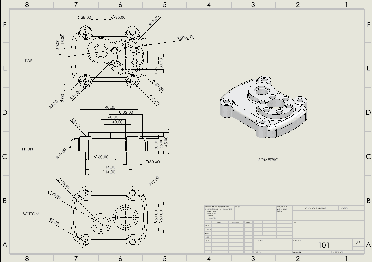
The "Fast" Drawing Generation feature, powered by Opus 4.8 and the MecAgent Copilot, is an instant extraction tool designed to create engineering drawings within seconds. From the moment it is launched, the assistant allows users to directly apply their company’s official template or a pre-filled drawing format, while configuring the sheet size (A3, B-series, etc.) and international drafting standards (ISO, ASME).
The system immediately generates the three main standard views (top, front, bottom), either following conventional projection rules or intelligently selected by the Copilot to best highlight the part’s geometry. This method fully supports multi-body parts but focuses strictly on the essentials: extracting measurements and standard information (nominal dimensions, diameters, basic radii) to produce a clean and editable deliverable.
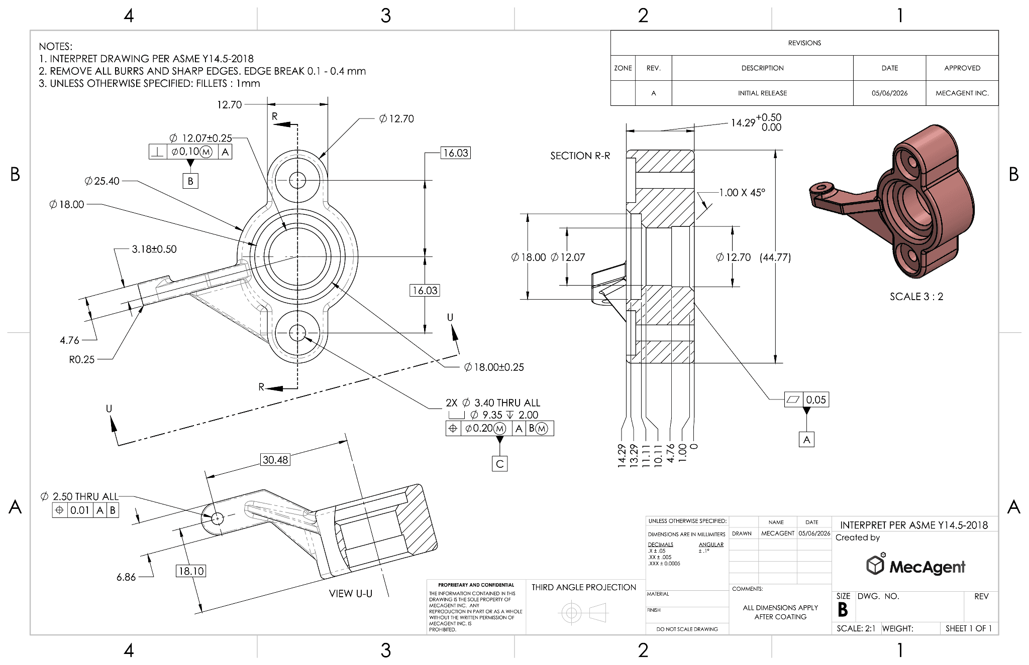
The Background Drawing Agent leverages the same Opus 4.8 / MecAgent combination, but operates as an asynchronous background process designed to generate a fully comprehensive engineering drawing. Depending on the complexity of the part, the background processing time can range from 1 to 24 hours.
Designed for high-precision manufacturing environments, this AI agent performs an in-depth analysis of the part to automatically apply a complete set of complex GD&T (Geometric Dimensioning and Tolerancing) annotations, fully compliant with ASME and ISO standards. The final deliverable is generated either as a PDF or directly in its native CAD format, while maintaining full associativity: any modification to the 3D geometry automatically updates the technical drawing.
Finally, MecAgent integrates an ultra-smooth interactive 3D viewer that allows users to manipulate the part (orbit, zoom) and directly click on specific faces to graphically select reference surfaces (datums) and critical features, all without slowing down the active working session.
Drawing Generation Benchmark: Fast vs Background
Technical Criterion / Element | “Fast” Approach (MecAgent & Opus 4.8) | “Background” Approach (MecAgent & Opus 4.8) | Impact on Designer & Manufacturing |
Execution Time | ~10 seconds (instantaneous) | ~15 hours (asynchronous / background task) | Fast: Immediate time savings. Background: Long computation but invisible to the user (zero freezing). |
Completeness Score | 3/10 (concept drawing) | 9.1/10 (production-ready) | Clear trade-off depending on final usage: visual validation vs. real manufacturing. |
Complex Section Views (SECTION R-R and VIEW U-U) | Limited: only top, front, and bottom views. No cutting planes or angled projected views. | Automatic: the agent analyzes 3D geometry and inclined alignment, then generates and displays section views and auxiliary projections. | The designer remains 100% productive on their workstation while heavy geometry calculations are processed. |
Specifications (GD&T) ([⌖|0.10(M)|A], Datums A, B, C) | Not available: limited to extracting nominal linear dimensions. All functional tolerancing must be manually added. | Intelligent: Automatic and semantic extraction of PMI/MBD annotations from the 3D model to create standardized tolerance frames. | Maximum security: eliminates the risk of omitting or incorrectly entering a critical tolerance. |
Isometric Rendering (3D View, Scale 3:2) | Simple wireframe: no texture support. | Realistic: support for selected real materials (copper/bronze appearance) and hatch management. | Operators on the shop floor and customers can immediately understand the final shape and appearance of the part. |
Notes & Engineering Rules (Notes 1, 2, 3 in upper-left corner) | Empty / Standard: a generic template is applied. Requires time-consuming manual editing. | Context-aware: the agent automatically inserts most relevant notes (ASME Y14.5-2018 standards, deburring requirements, fillet radii). | Standardization: automated compliance with company quality standards. |
Title Block & Revisions (Revision table, Rev A) | Static: supports customer template integration. Includes title and part name. | Synchronized: supports customer template integration. Automatically includes title, part name, and material. | Complete traceability between the official drawing document and the central database. |
Stacked Dimensions (Ordered dimension chains) | Manual: the designer must align dimensions themselves, sometimes creating visual overlap and clutter. | Automated: intelligent detection of reference lines and automatic stacking with standardized spacing. | A clean, well-organized drawing immediately understandable by the metrology department. |
Conclusion
The integration of Claude Opus 4.8 + MecAgent 1.2 primarily represents a significant advancement in terms of reliability, automation, and design assistance.
With MecAgent Copilot, Opus 4.8 improves performance in the following areas:
Analysis of technical scripts;
Automation of repetitive CAD tasks;
Generation of macros and parametric features;
Documentation and validation of design processes.
However, complex geometric design remains an area that requires close human supervision. For mechanical engineering design offices, Claude Opus 4.8 combined with MecAgent 1.2 should be considered an engineering accelerator rather than an autonomous designer. When integrated into MecAgent, it helps secure and accelerate workflows while keeping the engineer at the center of decision-making.

MecAgent Inc.

Other articles you might like
Learn how to increase your productivity with calendars


