
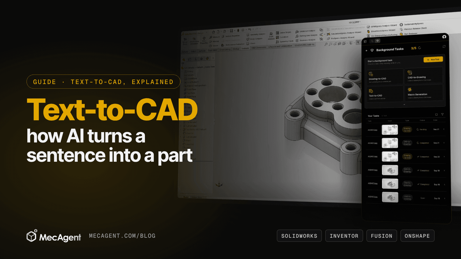
Type a sentence, get a part. That is the promise of text-to-CAD, and most big CAD vendors are now chasing it. Dassault Systèmes lists "Intent to CAD" among the pillars of SOLIDWORKS AI, Autodesk trains foundation models on real CAD geometry, and Inventor now opens a live session to outside AI agents.
But the results vary wildly. Some tools hand you a mesh you can only look at. Others give you a solid with no history. The useful ones give you what an engineer would have built: a native part with a feature tree you can edit.
This guide explains how AI turns text into CAD, what the newest research shows, where it runs today in SOLIDWORKS, Inventor, Fusion, Onshape and NX, and how to write prompts that come back as editable parts. Every example prompt runs in MecAgent, the AI CAD agent that models parts live in SOLIDWORKS.
New this month: Autodesk's Inventor 2027.2 notes, published November 3, 2026, describe a local MCP server that lets outside AI agents inspect and change a model in an open Inventor session, with the same tools as the built-in Autodesk Assistant. Autodesk's example builds a 3D model from an attached drawing in one prompt (Autodesk). The same week, new arXiv papers brought physics checks and design intent into AI-generated CAD.
What Is Text-to-CAD?
Text-to-CAD is the use of AI to create a CAD model from a written description: shapes, dimensions, quantities and constraints. Depending on the approach, you get back a mesh, a solid or a fully parametric part.
A mesh (STL, OBJ) is a shell of triangles: fine for a render or a quick 3D print, useless when a bore has to go from Ø20 to Ø22. A parametric part is a feature tree: sketches, extrudes, holes and fillets you can edit, drive with equations and detail on a drawing.
The first test of any tool is simple: open the result and change a dimension. If you can't, you have a shape, not a design.
The 4 Ways AI Turns Text into CAD
Every tool follows one of four approaches, each with a different output.
| Approach | What comes back | Editable? | Good for | Watch out for |
|---|---|---|---|---|
| 1. Text-to-3D mesh | Triangles (STL, OBJ) | No dimensions, no features | Concepts, renders, quick prints | Useless for engineering changes |
| 2. Direct solid (B-rep) generation | An exact solid, often exchanged as STEP | Direct edits; history only in some cases | Early shape exploration | Design intent often missing |
| 3. CAD code generation | A script that a CAD kernel runs | Yes, through the script's parameters | Part families, custom features | Code that runs can still be the wrong part |
| 4. An agent in your CAD software | Native features in your own CAD file | Yes, a native feature tree | Real parts in real assemblies | Needs a precise brief and a review |
1. Text-to-3D mesh
General 3D generators learn from shapes and images, not engineering intent. Their meshes have no dimensions or features to edit: fine for a mood board, not for the machine shop.
2. Direct solid (B-rep) generation
A boundary representation (B-rep) is the exact description of faces and edges that every CAD kernel works with. Autodesk's neural CAD foundation models are trained on real CAD objects to generate this kind of precise geometry. Autodesk says the output is editable in parametric tools and that, for specific tasks, the models will produce the full history of CAD commands (Autodesk). Neural CAD also powers features in Fusion: at Autodesk University 2026, Autodesk presented AutoTimeline, which converts imported geometry into editable parametric parts (Autodesk).
3. CAD code generation
Here the AI writes a program, and a CAD kernel turns it into geometry. Much of the research takes this route, using open-source CAD scripting languages that language models already write well.
Onshape uses its own language. Its FeatureScript MCP Server, launched in August 2026 through Onshape Labs, lets engineers describe a custom feature in plain language while a coding model such as Claude, ChatGPT or Gemini builds, tests and refines it in FeatureScript. David Katzman, who runs Onshape and Arena at PTC, sees the future as "not simply text-to-CAD, but text-to-code-to-CAD" (PTC).
Parameters live in the script, so the part stays editable. But a script that runs proves nothing about whether the part is right.
4. An agent in your CAD software
Here an AI agent plans the part, builds it feature by feature in your own CAD software through its programming interface, checks the result and corrects itself. You get a native part with a feature tree your team already knows how to edit.
This is how MecAgent works in SOLIDWORKS, and the CAD vendors are moving the same way, from Inventor's MCP server to SOLIDWORKS Design, where Dassault Systèmes' LEO companion takes prompts to generate assembly structures and add parametric features to STEP files (SOLIDWORKS).
What the Latest Research Shows
Four recent arXiv papers show where the field is going, and what to ask of any tool you try.
| Paper | The idea | Why it matters to you |
|---|---|---|
| Intent2CAD (NeurIPS 2026) | Train on design intent: features, reusable parameters and relations | Parts you can edit, not just regenerate |
| CRAFT (IEEE ICLAD 2026) | Agents plan, render, check and fix a parametric script | Self-correction catches geometric errors |
| PhyCAD (November 2026) | Finite element analysis checks generated parts during training | A part that looks right can fail under load |
| RealCADBench (September 2026) | 12,632 tasks built from real industrial design intents | Code that runs is not a correct part |
Design intent is the new target. Intent2CAD argues that a useful CAD program must expose reusable structure, not just reproduce a shape. Its authors rebuilt 100,000 training programs around features, parameters and relations, which made generation more reliable and improved zero-shot edits that keep design intent (arXiv).
Self-correction works. In CRAFT, agents understand the request, plan the parameters, compile, render the part from several views, then find and fix geometric errors. Without task-specific training, it stays competitive with direct zero-shot generation while keeping more parametric structure (arXiv).
Physics enters the loop. PhyCAD, posted November 6, 2026, pairs parts with loads and physical constraints. Its verifier runs the CAD code, checks the geometry and runs a finite element analysis, so training rewards parts that meet the physical constraints, not just the shape (arXiv).
Benchmarks are getting stricter. RealCADBench, from JD Industrial, gives models text, 2D drawings, product photos or renders, then scores whether their code runs, two measures of geometric overlap and a visual judge. No model leads on all four, and the authors conclude that execution alone is not enough to judge realistic CAD modeling (arXiv).
The lesson: don't stop at "it generated something." Ask whether the part matches your dimensions, whether the feature tree carries your design intent, and whether the tool checks its own work.
AI Part Generation in SOLIDWORKS, Inventor, Fusion, Onshape and NX
Every major CAD vendor now ships AI, and each takes its own route. Here is where each platform stands as of November 2026.
| CAD software | The vendor's own AI | With MecAgent |
|---|---|---|
| SOLIDWORKS | "Intent to CAD" is a pillar of SOLIDWORKS AI. Dassault Systèmes says SOLIDWORKS Design 2027 turns prompts, images and legacy drawings into geometry, with AI usage metered in tokens (Dassault Systèmes) | Native and live in SOLIDWORKS 2024, 2025 and 2026, with an editable feature tree |
| Autodesk Inventor | Autodesk Assistant writes iLogic rules from a prompt; Inventor 2027.2 adds a local MCP server for outside agents | Web app, STEP output; native add-in next on the roadmap |
| Autodesk Fusion (formerly Fusion 360) | Neural CAD features, with AutoTimeline presented at Autodesk University 2026 | Web app, STEP output |
| Onshape | FeatureScript MCP Server in Onshape Labs | Web app, STEP output |
| Siemens NX (now Designcenter) | Designcenter Copilot: AI-powered guidance in the workflow (Siemens) | Web app, STEP output; native add-in planned |
CATIA, PTC Creo and Solid Edge users can also use the MecAgent web app and open the STEP result. Native add-ins are on the roadmap, Inventor first, then Siemens NX and CATIA (user guide).
How to Get an Editable Part from Text-to-CAD: 5 Steps
The model matters, but the brief matters more. These steps work with any agent that builds real features.
Step 1: Write the prompt like a drawing
AI fills every gap with a guess. Give it what a drawing gives a machinist: dimensions, quantities, positions, references. "Add holes in the corners of the plate" leaves everything open. This leaves nothing:
Add four Ø5 mm through holes, 10 mm from each edge, at the corners of the plate.
More examples are in the guide on how to prompt.
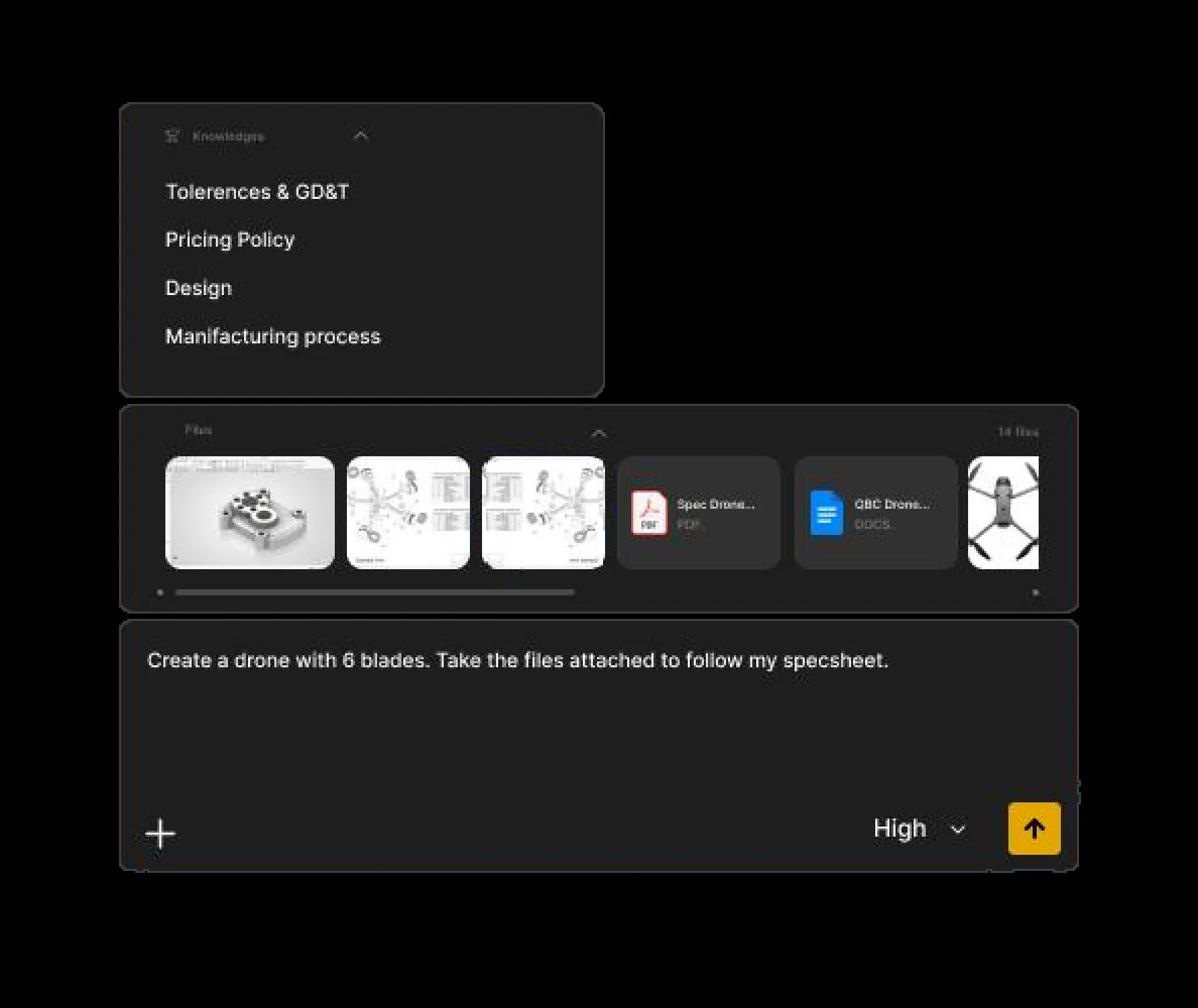
Step 2: Attach the spec sheet instead of retyping it
If the requirements already exist in a PDF, a spreadsheet, a photo or a sketch, attach them: the agent then works from your source of truth, with no transcription errors.
Create a drone with 6 blades. Take the files attached to follow my spec sheet.
Step 3: Build the base first, then the details
Complex parts fail when you ask for everything at once. Build the base, check it, then add the details:
Create a 500 × 200 × 2 mm plate.
Add Ø5 mm holes 10 mm from the edges at each corner.
Add a Ø50 mm hole at the center.
Step 4: Check the feature tree, not just the shape
A part can look right and still be wrong. Measure the critical dimensions, compare the mass with what you expect and make sure the sketches are fully defined. Then make the tree readable for the next engineer:
Rename each feature in the tree with a meaningful name based on the geometry it creates.
Step 5: Make the part reusable
A generated part pays off when it drives a family. Turn the key dimensions into global variables and configurations, so the next variant is a value change, not a new prompt.
Create a global variable for the arm length and three configurations: 200, 250 and 300 mm.
If you build the same kind of part every week, turn the steps into a macro: see Text-to-Macro-to-CAD.
5 Common Mistakes to Avoid
- Asking for a product, not a part. "Create a car." is a high-level intent with no dimensions. Break it down into parts you could put on a drawing.
- Leaving out references. "The top face", "the Ø20 bore" or "Plane1" tells the AI where to work. Selecting the face in your CAD software works too.
- Expecting class-A surfaces from a vague prompt. Complex freeform or class-A surfacing from a loose description is still out of reach.
- Forgetting company rules. AI can't apply tolerancing rules, preferred materials or naming conventions it was never given. In MecAgent, store them once as General Knowledges, folders of your own documents attached to any request.
- Releasing without review. MecAgent's own guide is explicit: parts and drawings need an engineer's review before release, and MecAgent does not guarantee certification or regulatory compliance.
Text-to-CAD with MecAgent: Live or in the Background
MecAgent is an AI CAD agent for mechanical engineers: you describe the part, it plans the work, builds it in your CAD software and reports back. It runs Text-to-CAD two ways.
Live, in SOLIDWORKS. The CAD Agent models the part in your open session, from text or a spec sheet, with an editable feature tree. You follow its Task Progress, then refine in the same conversation: "make the wall 3 mm", "add a fillet on the selected edges."
In the background. Send a written brief or a spec sheet as a Background Task and keep modeling. The part lands in your outputs. In Deliver for, pick your SOLIDWORKS version, or Other CAD Software to get a STEP file.
A rectangular aluminum enclosure 120 × 80 × 40 mm, 2 mm walls, open top, four M3 bosses Ø6 mm in the corners, 1 mm fillets on outer edges.
Why not a general chatbot? General AI tools are not built to operate CAD software: they guess API calls and produce code that fails. MecAgent was trained on real CAD workflows and hundreds of thousands of CAD automations, and acts through dedicated CAD tools: it reads the model, runs the features, checks the result and corrects itself.
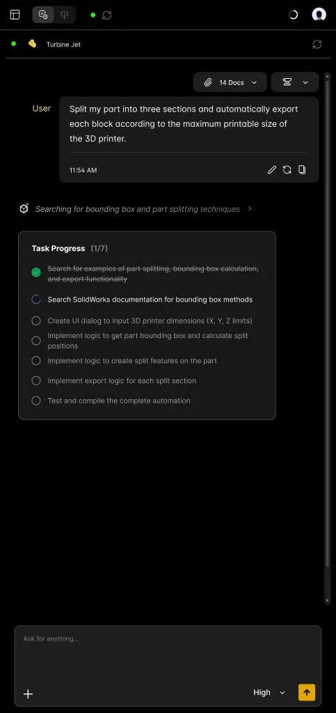
To start, download MecAgent with a free account (Windows 10 or 11, SOLIDWORKS 2024, 2025 or 2026), or use the web app for other CAD software. Model a part you have already drawn and compare. Every use case is filmed in the demo library, and AI for SOLIDWORKS: 15 tasks shows what else the agent can take off your plate.
Bottom Line
Getting a 3D shape from a sentence is the easy part. What matters to an engineer is a model you can edit, constrain, detail and reuse. Judge every text-to-CAD tool by the feature tree it hands back, write prompts like drawings, build in steps, and check the result like a colleague's model before release.
FAQ
What is text-to-CAD?
It is AI that creates a CAD model from a written description. The result can be a mesh, an exact solid (often exchanged as STEP) or a parametric part with an editable feature tree; for engineering work, the parametric part is the one that counts.
Can AI generate a parametric CAD model from text?
Yes. Code-generation approaches keep the parameters in the script, and agents working inside CAD software build native features. MecAgent's Text-to-CAD builds the part feature by feature in SOLIDWORKS, so you can change any dimension afterward.
What is the difference between text-to-CAD and text-to-3D?
Text-to-3D generators produce meshes for visuals, games or 3D printing, with no dimensions or features to edit. Text-to-CAD aims at engineering geometry: exact solids and, ideally, a feature tree with the dimensions and relations an engineer would define.
Which CAD software supports text-to-CAD?
Several CAD vendors are building it, each in its own way, from "Intent to CAD" in SOLIDWORKS AI to neural CAD in Fusion and MCP servers in Inventor and Onshape. MecAgent runs natively in SOLIDWORKS 2024 to 2026 and delivers STEP files for other CAD software through its web app.
Are AI-generated CAD models accurate enough for manufacturing?
For well-specified mechanical parts, AI gives you a strong first model, not a released one. Check critical dimensions, tolerances and GD&T before release, as you would for any model.
Can AI turn a drawing into a CAD model?
Yes. MecAgent's Drawing-to-CAD turns a PDF or image drawing into an editable part as a background task. A dimension that is illegible on a scan stays a guess, so verify the critical values.
Sources
- Autodesk: What's new in Inventor 2027.2 (November 3, 2026), Neural CAD, AI at AU 2026 (September 15, 2026)
- Dassault Systèmes: What's new in SOLIDWORKS Design 2027, SOLIDWORKS AI virtual companions
- PTC: Onshape FeatureScript MCP Server (August 13, 2026)
- Siemens: Designcenter X NX tips and tricks: Copilot (May 12, 2026)
- arXiv: Intent2CAD (Yang et al.), CRAFT (Rafi et al.), PhyCAD (Cui et al.), RealCADBench (Li et al.)