

Milling
A spinning multi-edge cutter moves over a fixed part
Milling carves a part with a spinning cutter that has several teeth, while the workpiece is moved past it. It makes flat faces, slots, pockets and almost any 3D shape: engine block faces, plastic injection molds and the aluminum bodies of many laptops are milled. It is the most versatile machining process.
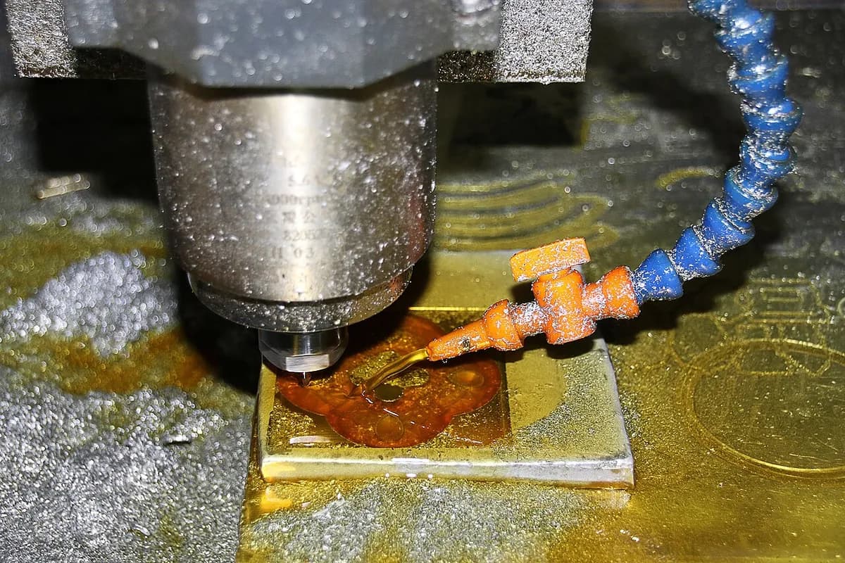
Milling in a minute, by MecMade
How it works
Clamp the block. A vise (a screw-driven clamp) or bolts hold the workpiece firmly on the machine table, because cutting forces are large.
Spin the cutter. The spindle turns a cutter with several cutting edges (teeth). Speeds run from a few hundred rpm (revolutions per minute) for large cutters in steel to 20,000 or more for small ones in aluminum.
Set the depth. The cutter is lowered to the depth of cut, from a few tenths of a millimeter for finishing to several millimeters for roughing.
Feed the part. The table moves the part under the cutter. Each tooth takes a small bite, typically 0.05–0.2 mm thick, and flings it off as a chip.
Follow a path. A CNC program (computer numerical control: the machine follows coded coordinates) steers the cutter in X, Y and Z. It traces outlines and clears pockets in many passes, roughing first and finishing last, and swaps cutters automatically.
Key facts
- Materials
- Metals (aluminum, steel, titanium, brass), plastics, wood, composites
- Typical parts
- Brackets, housings, engine blocks, molds and dies, gearbox cases, prototypes
- Part size
- From a few millimeters to several meters on large gantry machines (aircraft wing parts)
- Precision
- Typically ±0.01–0.05 mm; about ±0.005 mm on precise machines
- Surface finish
- Typically Ra 0.8–3.2 µm (Ra = average roughness; 1 µm is a thousandth of a millimeter), with visible toolpath lines
- Batch size it suits
- One-offs and prototypes up to thousands of parts
- Tooling and machine cost
- Cutters cost tens to hundreds of dollars; machines run from a few thousand dollars (manual) to hundreds of thousands or more (5-axis CNC)
- Speed
- Minutes to hours per part, depending on how much material must come out
Strengths and limits
Strengths
- Makes almost any shape: flat faces, slots, pockets, 3D surfaces
- No part-specific tooling: a new design only needs a new program
- Accurate and repeatable, easy to automate
- Works on most solid materials
Limits
- Slower and costlier per part than casting or molding at high volume
- Can turn most of the starting block into chips
- Inside corners always keep a radius, because the cutter is round
- Deep, narrow cavities are hard: long, thin cutters bend and vibrate
Where it's used
- AerospaceWing ribs and spars, engine casings, brackets machined from solid aluminum or titanium
- AutomotiveEngine blocks and cylinder heads (flat faces), gearbox housings, prototypes
- ToolingInjection molds, die-casting dies, stamping dies
- ElectronicsLaptop and phone bodies, heat sinks, enclosures
- MedicalKnee and hip implants, surgical instruments
How to recognize it
- Fine parallel lines or overlapping arcs on flat faces: the paths of the cutter.
- Rounded inside corners on pockets, matching the cutter's radius.
- Large circular swirls on big flat faces, and tiny ridges (scallops) on curved 3D surfaces.
Compare with
Watch it
Autodesk Fusion · Milling basics for beginners
Sandvik Coromant · A close-up of a milling cutter in action
DMG MORI · A 5-axis machining center (a CNC mill that can also tilt the part), shown by its maker
Practical Machinist · Real 5-axis cuts carving complex parts
See real photos
- Wikipedia: Milling (machining) — cutters, milling machines and machining centers
- Wikimedia Commons photo search
Remember
- In milling the cutter spins and the machine moves the part or the cutter along a programmed path.
- Each tooth takes a small bite, so a cutter with more teeth can feed faster.
- Rounded inside corners and fine path lines are the signature of a milled part.
More in Machining
All 100 processes
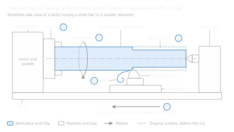 5.1ShortTurning (lathe)The part spins; a single-point tool cuts itOpen the lesson
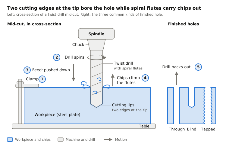
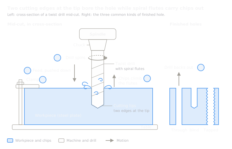 5.3ShortDrillingA spinning twist drill plunges into the partOpen the lesson
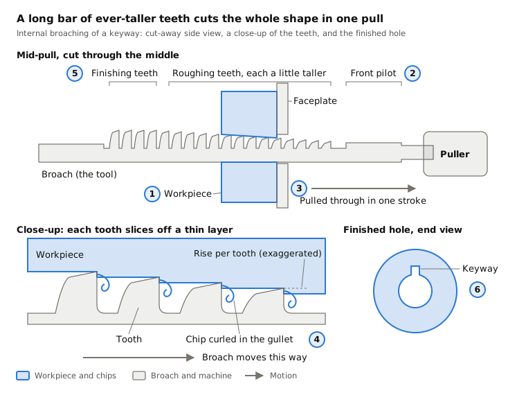
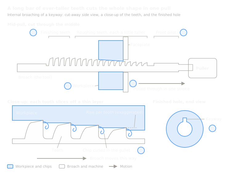 5.4BroachingA long toothed bar is pulled through or across in one strokeOpen the lesson
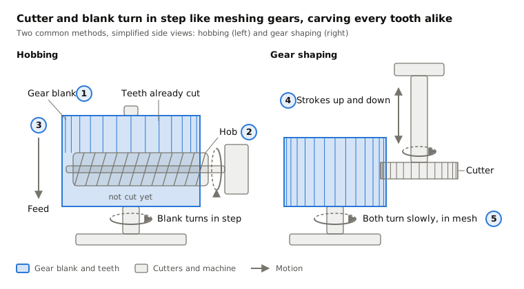
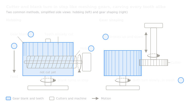 5.5Gear cutting (hobbing, shaping)Hobs or shaper cutters generate gear teethOpen the lesson
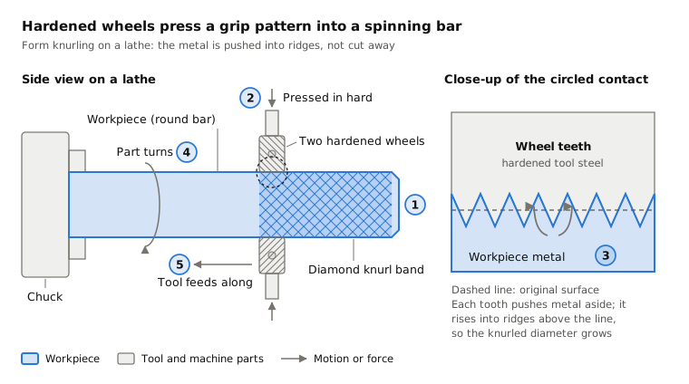
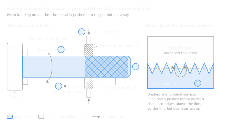 5.6KnurlingHardened wheels press a grip pattern into a turning partOpen the lesson
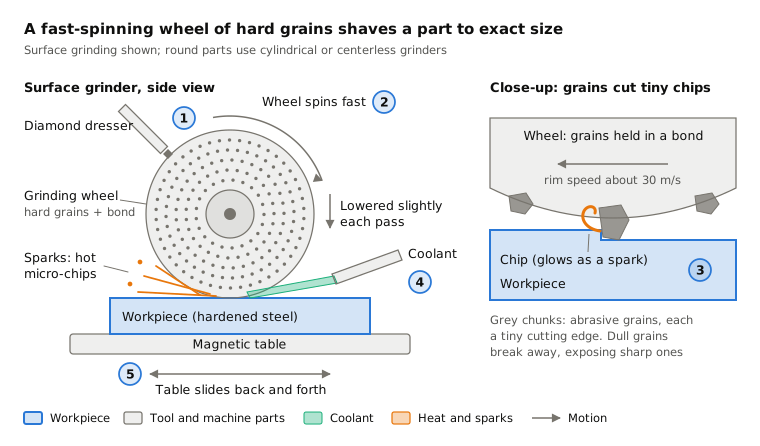
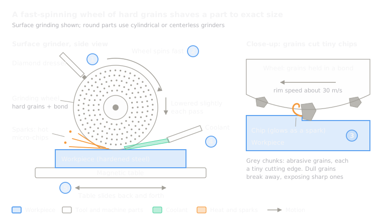 5.7GrindingA fast wheel of hard grains shaves the surfaceOpen the lesson
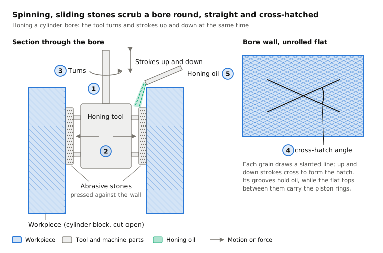
 5.8HoningStones turn and stroke inside a boreOpen the lesson
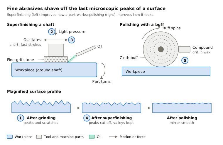
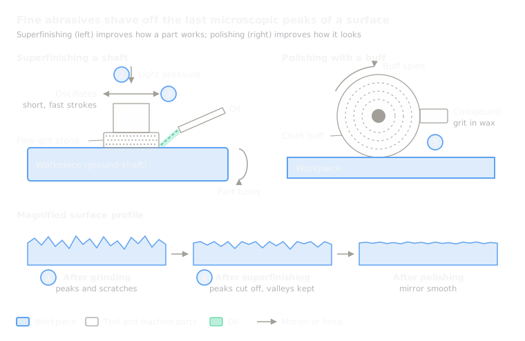 5.9Superfinishing and polishingFine stones or buffs remove the last microscopic peaksOpen the lesson
Try it
Put AI to work in your CAD.
Model parts, generate drawings and automate the repetitive work inside your CAD software.