

Turning (lathe)
The part spins; a single-point tool cuts it
Turning makes round parts: a lathe (a machine that spins the workpiece) rotates a bar while a single sharp tool slides along it and shaves off material. A wooden baseball bat, a table leg and the steel shaft inside an electric motor are all turned. It is the standard way to give a part an accurate diameter.
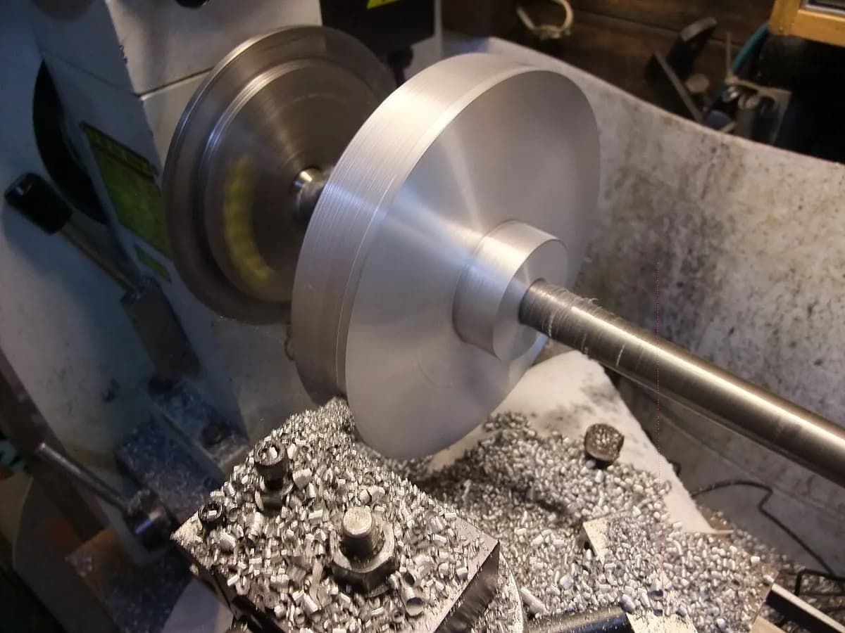
Turning (lathe) in a minute, by MecMade
How it works
Clamp the part. The bar is gripped in a chuck (a rotating clamp with jaws) on the headstock, the motor end of the lathe. A tailstock center (a pointed support at the far end) steadies long parts.
Spin it. The spindle turns the part, typically at a few hundred to a few thousand rpm (revolutions per minute). Small diameters and soft metals spin faster.
Set the depth of cut. The tool moves in toward the axis by the depth of cut (how deep it bites), typically 1–4 mm for roughing and 0.1–0.5 mm for the finishing pass.
Feed the tool along. The carriage (the sliding tool holder) moves the tool parallel to the axis at the feed rate, typically 0.05–0.5 mm per revolution.
Peel off the chip. The tool shears the outer layer into a chip and leaves a smaller, perfectly round diameter behind. The same lathe can also face the end flat and cut grooves or threads. It can bore (enlarge a hole from inside) and part off (cut the finished piece free).
Key facts
- Materials
- Nearly all metals (steel, aluminum, brass, titanium), plus plastics and wood
- Typical parts
- Shafts, pins, bushings (sleeves), pulleys, threaded fittings, knobs
- Part size
- From watch parts under 1 mm across to rolls and shafts several meters long
- Precision
- Typically ±0.01–0.05 mm on diameters; about ±0.005 mm with care
- Surface finish
- Typically Ra 0.8–3.2 µm (Ra = average roughness; 1 µm is a thousandth of a millimeter), with fine feed marks
- Batch size it suits
- One-offs to millions; automatic lathes with bar feeders run unattended for high volume
- Tooling and machine cost
- Inserts (replaceable carbide tool tips) cost a few dollars each; lathes run from a few thousand dollars (manual) to tens or hundreds of thousands (CNC, computer-controlled)
- Speed
- Seconds to a few minutes per small part; hours for a large shaft
Strengths and limits
Strengths
- Very accurate diameters, all on one shared axis
- Works on almost any material that can be cut
- Cheap, standard tools; no part-specific tooling
- Easy to automate with bar feeders and CNC
Limits
- Only round shapes, unless the lathe also carries spinning tools
- Turns part of the bar into chips (recyclable, but still waste)
- Long, thin parts bend and vibrate unless supported
- For millions of simple parts, forming (cold heading) is faster and wastes less
Where it's used
- AutomotiveShafts, wheel hubs, brake discs, valve parts
- AerospaceLanding gear parts, engine shafts, hydraulic fittings
- Energy and heavy industryTurbine rotors, pump shafts, steel-mill rolls
- MedicalBone screws, implant pins, dental implants
- Everyday goodsPen barrels, knobs, furniture legs, baseball bats
How to recognize it
- Fine, evenly spaced rings or a spiral running around round surfaces: the feed marks of the tool.
- Flat ends with a pattern of circles around the center, sometimes with a tiny nub or swirl left in the middle.
- Steps, grooves, chamfers (small bevels on edges) and threads that all line up perfectly on one axis.
Compare with
Watch it
RAPID DIRECT · A plain explanation of how CNC turning works
WWU Engineering and Design · The basic operations, demonstrated on a manual lathe
Haas Automation · Heavy roughing cuts on a large CNC lathe, with real chips
GlacernMachineTools · What series production looks like on a CNC lathe
See real photos
- Wikipedia: Lathe — freely licensed photos of old and modern lathes
- Wikipedia: Lathe center — live centers and turning between centers
- Wikimedia Commons photo search
Remember
- The part spins and the tool moves: that is why turning makes round shapes.
- Three settings control every cut: spindle speed, feed and depth of cut.
- Spiral feed marks and features on one shared axis give a turned part away.
More in Machining
All 100 processes
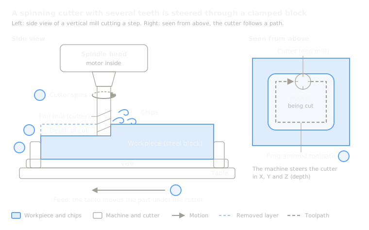 5.2ShortMillingA spinning multi-edge cutter moves over a fixed partOpen the lesson
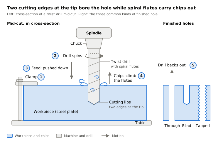
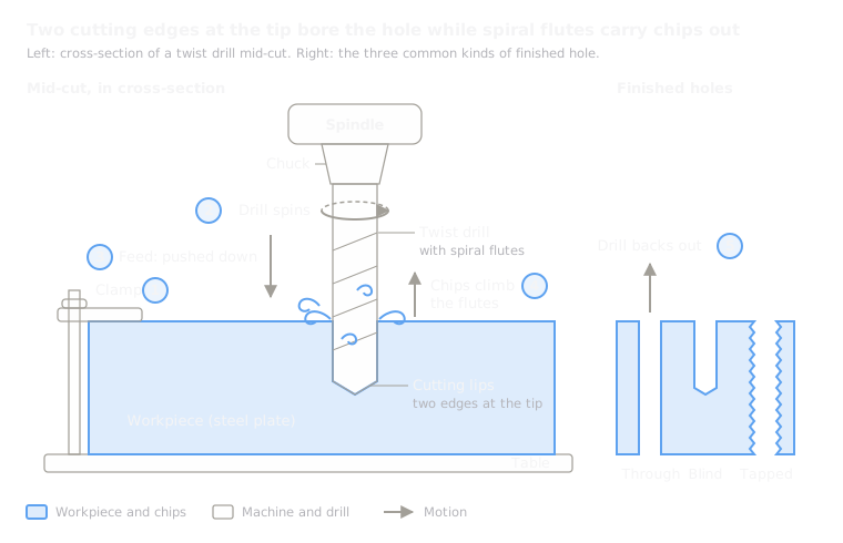 5.3ShortDrillingA spinning twist drill plunges into the partOpen the lesson
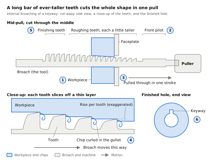
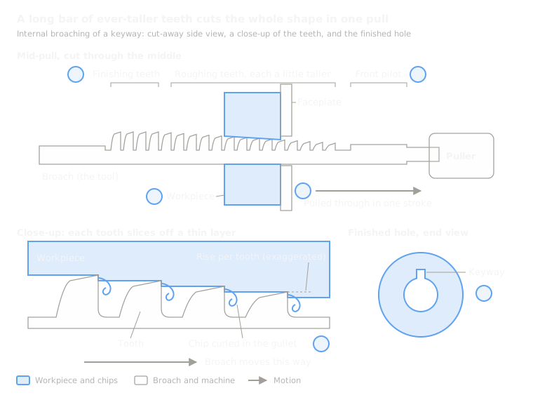 5.4BroachingA long toothed bar is pulled through or across in one strokeOpen the lesson
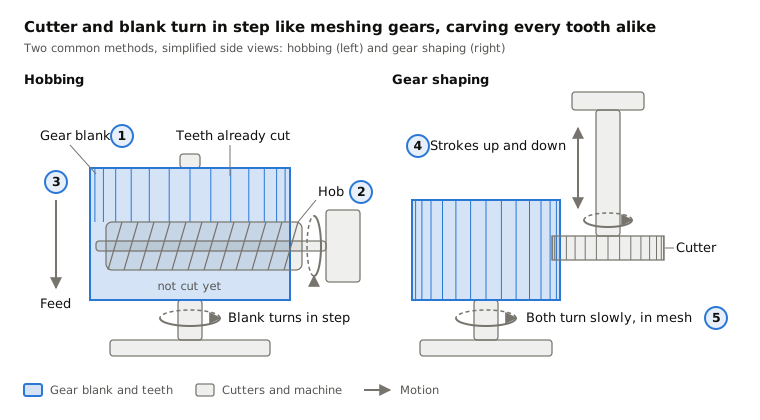
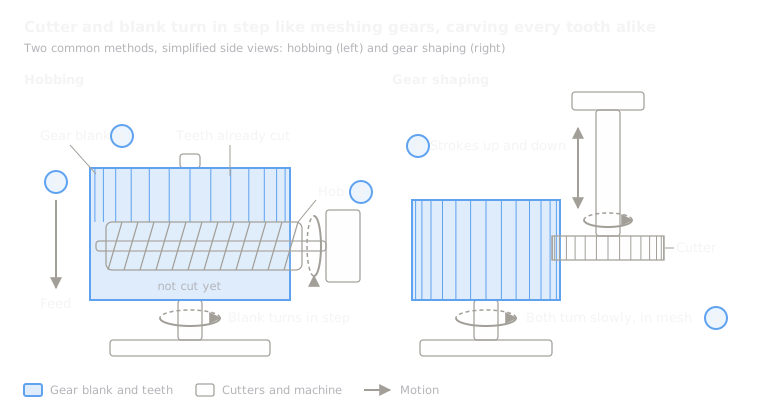 5.5Gear cutting (hobbing, shaping)Hobs or shaper cutters generate gear teethOpen the lesson
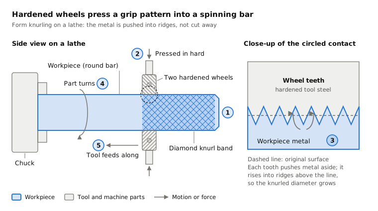
 5.6KnurlingHardened wheels press a grip pattern into a turning partOpen the lesson
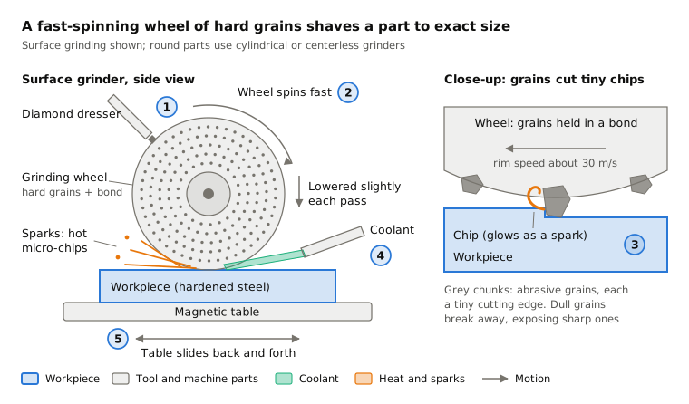
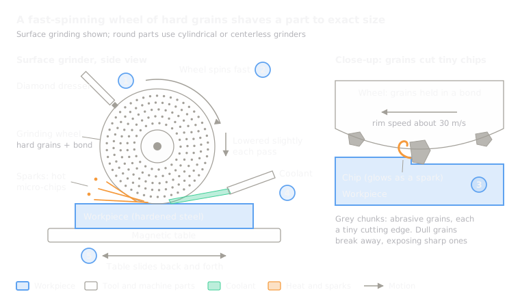 5.7GrindingA fast wheel of hard grains shaves the surfaceOpen the lesson
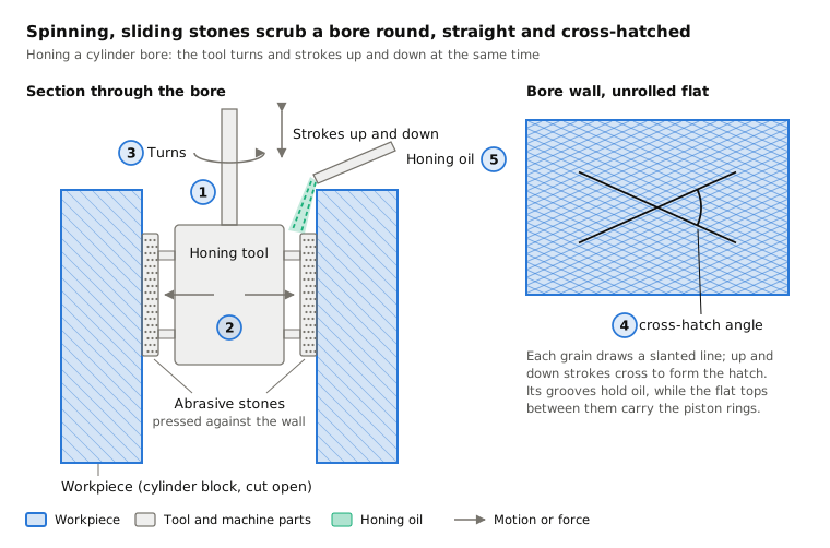
 5.8HoningStones turn and stroke inside a boreOpen the lesson
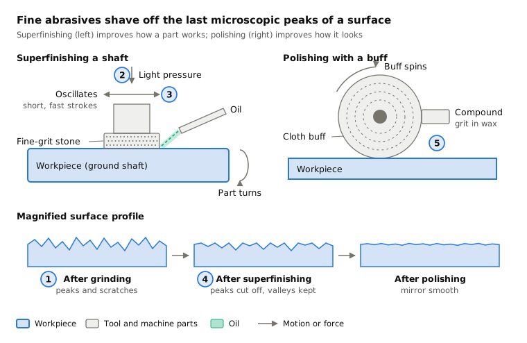
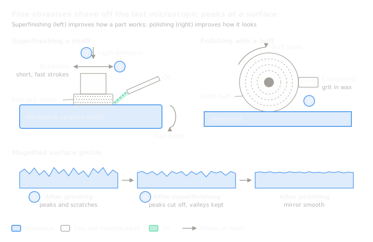 5.9Superfinishing and polishingFine stones or buffs remove the last microscopic peaksOpen the lesson
Try it
Put AI to work in your CAD.
Model parts, generate drawings and automate the repetitive work inside your CAD software.