

Incremental sheet forming
A round tool traces contours into clamped sheet, with no die
Incremental sheet forming (ISF) pushes a small round-tipped tool into a clamped metal sheet, shaping it one thin contour at a time. Picture a pen tracing ever-smaller circles into kitchen foil until the foil becomes a cup. No die (shaped steel tooling) is needed, so a one-off part can go from computer file to metal, often within a day.
How it works
Clamp the blank. A flat sheet (the blank) is clamped by its edges over a backing plate, a support with an opening shaped like the part's outline. Nothing sits under the area to be formed.
Press down one small step. A smooth, hardened rod with a ball-shaped end (the stylus, typically 5–20 mm across) pushes the sheet down by about 0.2–1 mm. A CNC machine (a computer-controlled machine tool) or an industrial robot holds and moves it.
Trace one contour. Software slices the 3D model into levels, like the layers of a 3D print, and the tool follows one level. Only a small patch under the tip bends and stretches at a time, so forces stay low; oil or grease cuts friction.
Step down and repeat. Lap after lap, often as one continuous spiral, the part grows deeper. The wall stretches and thins: a wall sloping 60° from flat ends up about half as thick as the original sheet.
Release and trim. The part is unclamped and the flat rim (the flange) is cut off. Metal springs back slightly (partly returns toward its old shape), so a measured correction pass or a heat treatment may follow.
Key facts
- Materials
- Aluminum, steel, stainless steel and titanium sheet, typically about 0.5–2 mm thick; some plastic sheets
- Typical parts
- Prototype body panels, covers and housings, custom medical plates, art and facade panels
- Part size
- From palm-sized up to about 2 m across, set by the machine's working area
- Precision
- About ±0.5–1 mm as formed; a few tenths of a millimeter with measured correction passes
- Surface finish
- Fine spiral tool marks on the tool side; the other side is smoother
- Batch size it suits
- One-offs to a few hundred parts
- Tooling and machine cost
- No die, and the stylus is cheap; the machine (CNC mill, robot cell or dedicated former) costs tens to hundreds of thousands of dollars
- Speed
- Slow: minutes to a few hours per part, depending on size and step height
Strengths and limits
Strengths
- No die: a design change is just a new program
- Small forces, so modest machines will do
- Metal often stretches further than in stamping before it cracks
- Ideal for one-offs, prototypes and custom fits
Limits
- Slow: minutes to hours per part, versus seconds in a press
- Steep walls (beyond about 60–70°) crack or need several passes
- Walls thin, and accuracy is lower than with a die
- Visible tool-path marks on one side
Where it's used
- AutomotivePrototype body panels, low-volume and restoration parts
- AerospacePrototype skins, ducts and brackets in small batches
- MedicalPatient-specific skull plates (cranial implants) in titanium
- Architecture and designFacade panels, lamps and art pieces
- Job shopsShort runs of covers and enclosures without paying for a die
How to recognize it
- Fine concentric rings or a spiral of tool marks on the inside (the tool side), a bit like the grooves of a vinyl record.
- Gently sloped walls that are thinner than the flat rim around them.
- Inside corners rounded to about the radius of the tool tip, never sharp.
- A flat flange or a trimmed edge where the sheet was clamped.
Compare with
Watch it
Eurecat · A research machine turning a flat sheet into a shell, lap by lap
NotStockPhoto · A tour and demo of a dedicated digital sheet-forming machine
Evology Manufacturing · How a job shop uses the process for real customer parts
이찬환 · The two-point variant, where the sheet is formed over a partial support
See real photos
- Wikipedia: Incremental sheet forming — overview of the principle and its variants; mostly text
- Wikimedia Commons photo search
Remember
- A small round tool replaces the die: the part's shape lives in a program, not in steel.
- The sheet is formed one shallow contour at a time, so it is slow but very flexible.
- Walls thin as they get steeper; about 60–70° is the practical limit in one pass.
More in Sheet and tube forming
All 100 processes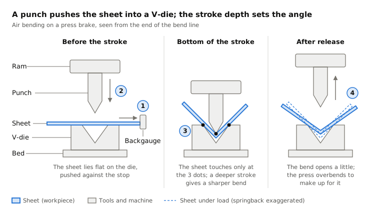
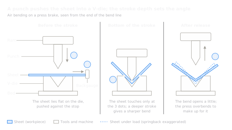 4.1Sheet metal bendingA press brake folds sheet along straight linesOpen the lesson
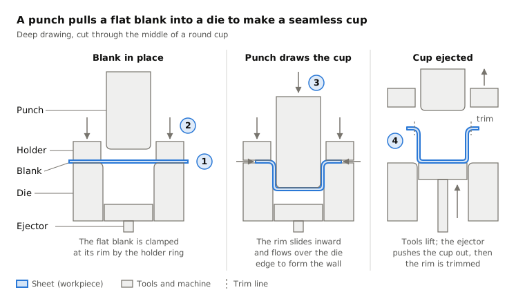
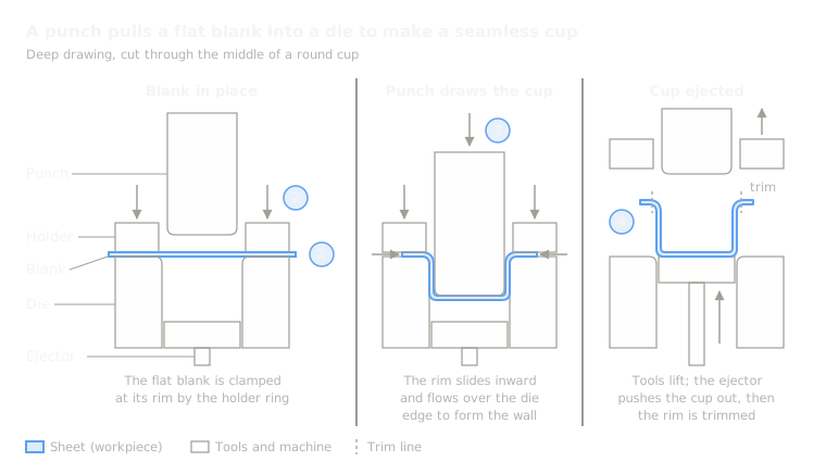 4.2ShortStamping and deep drawingMatched dies cut and press sheet into shape, often in a secondOpen the lesson
 4.3Metal spinningA roller presses a spinning disc over a formOpen the lesson
 4.4Flow formingRollers stretch a spinning tube thinner and longer over a mandrelOpen the lesson
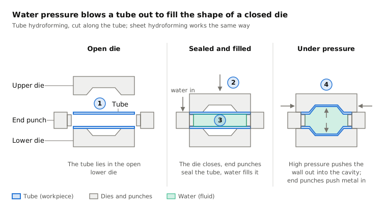
 4.5HydroformingFluid pressure pushes tube or sheet into a dieOpen the lesson
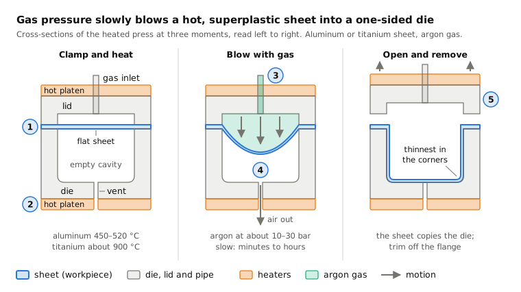
 4.7Superplastic formingHot gas blows a superplastic sheet into one dieOpen the lesson
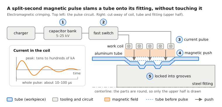
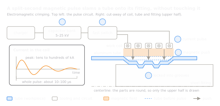 4.8Electromagnetic formingA magnetic pulse throws metal onto a fitting, without contactOpen the lesson
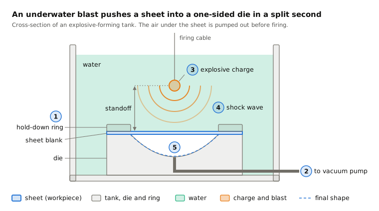
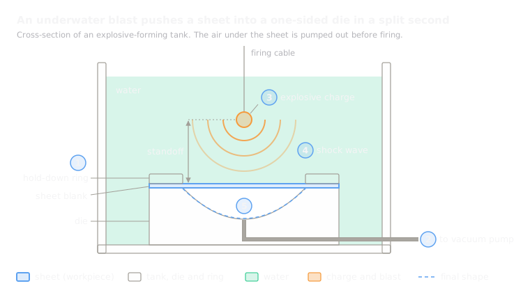 4.9Explosive formingAn underwater blast pushes sheet into one dieOpen the lesson
 4.10Laser peen formingLaser shots stretch one face so a plate curvesOpen the lesson
Try it
Put AI to work in your CAD.
Model parts, generate drawings and automate the repetitive work inside your CAD software.