

FDM (fused deposition modeling)
Extrudes molten plastic filament through a moving nozzle (material extrusion)
FDM (fused deposition modeling, also called FFF) builds a part by pushing melted plastic through a fine nozzle, layer upon layer. It is the desktop 3D printer behind phone stands, toy figures and replacement knobs. It matters because it turns a digital file into a real plastic part within hours, with no mold or tooling.
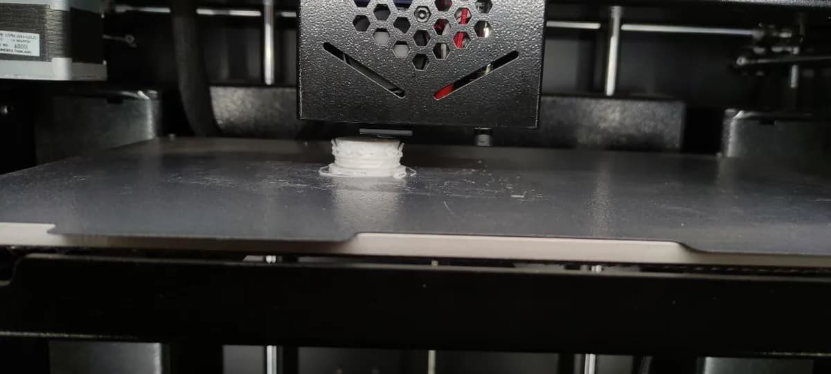
FDM (fused deposition modeling) in a minute, by MecMade
How it works
Slice the model. Software called a slicer cuts the 3D model into thin horizontal layers. It then writes the toolpath (the exact route the nozzle will follow in each layer).
Feed the filament. Drive gears grip a plastic wire called filament, usually 1.75 mm thick, and push it steadily into the hot end.
Melt it. A heater block warms the plastic to about 190–260 °C, depending on the material. It softens into a thick paste, like warm toothpaste.
Draw one layer. The head moves in X and Y and lays a bead through the nozzle, typically 0.4 mm wide. It traces the outer walls first, then fills the inside with a sparse pattern called infill.
Step up and repeat. The plate drops (or the head rises) by one layer height, typically 0.1–0.3 mm. The next layer fuses onto the still-warm one below, hundreds of times over.
Remove and clean up. Once cool, you take the part off the plate. Supports (temporary scaffolding printed under overhangs) snap off, and you can sand or paint the surface.
Key facts
- Materials
- Thermoplastics (plastics that soften when heated): PLA, PETG, ABS, ASA, flexible TPU, nylon, polycarbonate, fiber-filled grades; PEEK and ULTEM on industrial machines
- Typical parts
- Prototypes, enclosures, brackets, jigs and fixtures, spare parts, display models
- Part size
- Typically up to about 25 cm per side on desktop printers; industrial machines reach roughly 1 m
- Precision
- About ±0.2–0.5 mm (a few tenths of a millimeter); better on industrial machines
- Surface finish
- Visible layer lines and a ridged, matte surface; smooth only after sanding, filling or coating
- Batch size it suits
- 1 to a few hundred parts; print farms of many printers go higher
- Tooling and machine cost
- No tooling; desktop printers cost a few hundred to a few thousand dollars, industrial systems tens to hundreds of thousands
- Speed
- Slow: under an hour for a small clip, a day or more for a large part
Strengths and limits
Strengths
- The cheapest, most accessible way to make a plastic part from a file
- No tooling, so a design change costs nothing
- Real engineering plastics, including tough, heat-resistant and flexible ones
- Sparse infill makes light, material-saving parts
Limits
- Visible layer lines and a rough finish
- Weaker between layers than along them (anisotropic, meaning strength depends on direction)
- Overhangs need supports, which leave marks
- Slow, and the cost per part barely drops with quantity
Where it's used
- Product designConcept models and working prototypes of housings, clips and knobs
- ManufacturingJigs, fixtures, gauges and custom grippers for assembly lines
- Aerospace and automotivePrototypes, tooling, and low-volume interior parts in flame-retardant plastics
- HealthcareAnatomical models for surgery planning, custom orthotic parts
- Education and hobbyClassroom projects, cosplay props, household spare parts
How to recognize it
- Fine horizontal ridges on every side wall, like a stack of thin threads (layer lines).
- A "staircase" look on gently sloping or curved top surfaces.
- A small seam or bump where each layer started and ended, often lined up vertically.
- Rough patches or stubs under overhangs where supports were snapped off, and one very flat bottom face that sat on the build plate.
Compare with
Watch it
3Dnatives · The FDM principle explained for beginners
Protolabs · When FDM suits a prototype, with design tips
Protolabs · A part growing layer by layer, sped up
Strange Parts · A huge print farm making parts in production
See real photos
- Wikipedia: Fused filament fabrication — diagrams of the extrusion head, photos of printers and printed parts
- Wikimedia Commons photo search
Remember
- FDM melts a plastic filament and draws the part bead by bead, layer by layer.
- It is the cheapest route from a file to a real plastic part, but it is slow and shows layer lines.
- Parts are weakest between layers, so orient the print so loads run along the layers.
More in Additive manufacturing
All 100 processes
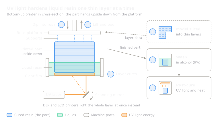 8.2Stereolithography (SLA/DLP)Hardens liquid resin layer by layer with a laser or projector (vat photopolymerization)Open the lesson
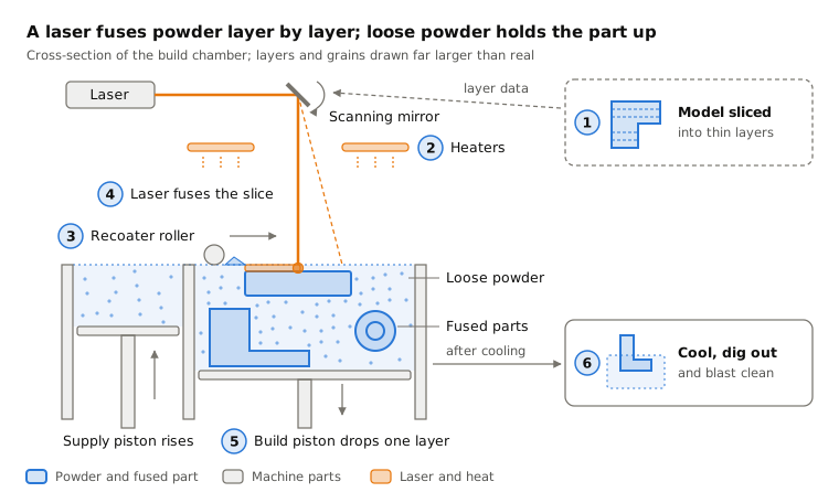
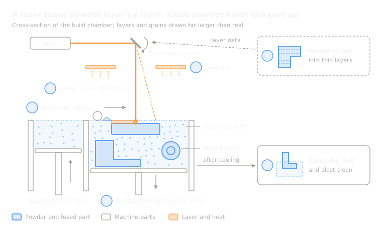 8.3Selective laser sintering (SLS)A laser fuses nylon powder in a bed; the loose powder supports the part (powder bed fusion)Open the lesson
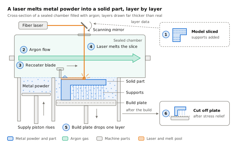
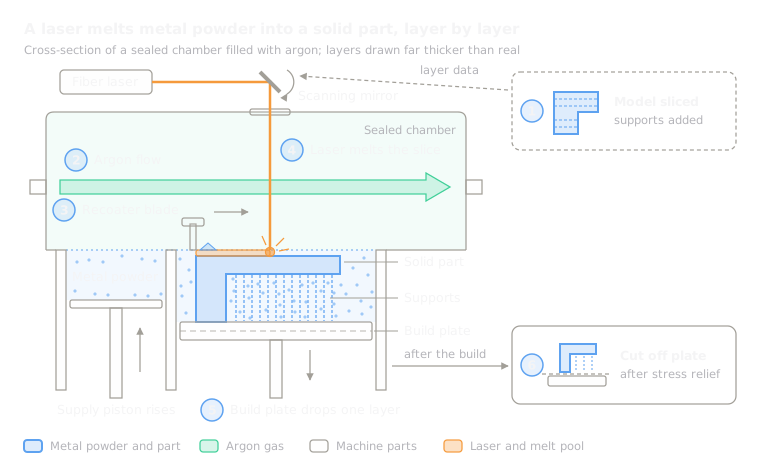 8.4Laser powder bed fusion (metal, SLM/DMLS)A laser melts thin layers of metal powder (powder bed fusion)Open the lesson
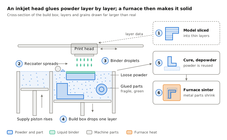
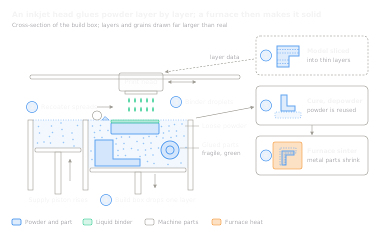 8.5Binder jettingInkjet heads glue powder, then the part is cured or sintered (binder jetting)Open the lesson
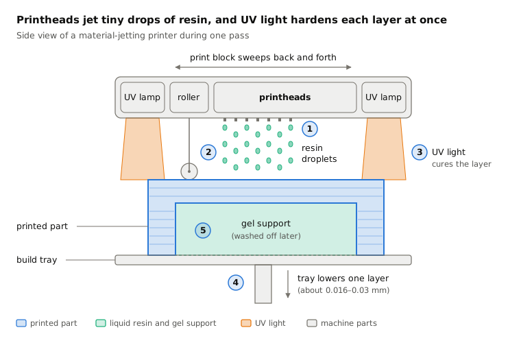
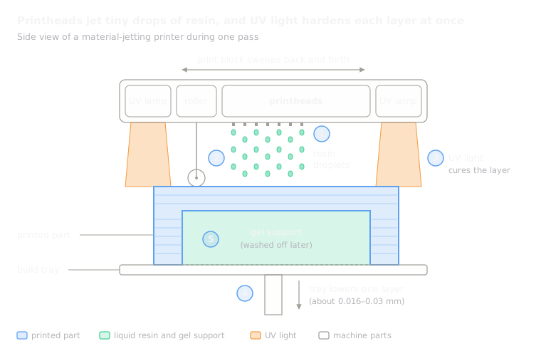 8.6Material jetting (PolyJet)Jets droplets of resin and cures them with UV light (material jetting)Open the lesson
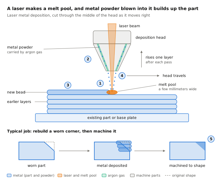
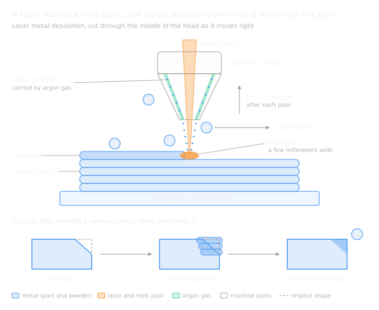 8.7Directed energy deposition (DED/LMD)A laser melts a pool on the part; blown powder adds metal (directed energy deposition)Open the lesson
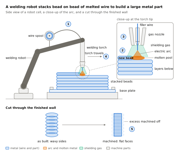
 8.8Wire arc additive manufacturing (WAAM)A welding robot stacks arc-melted wire into beads (directed energy deposition)Open the lesson
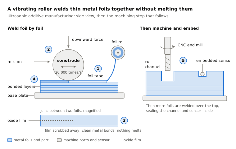
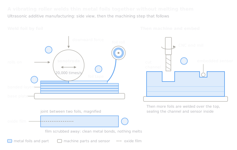 8.9Ultrasonic additive manufacturing (UAM)Ultrasonic vibration welds metal foils without melting, then a mill trims them (sheet lamination)Open the lesson
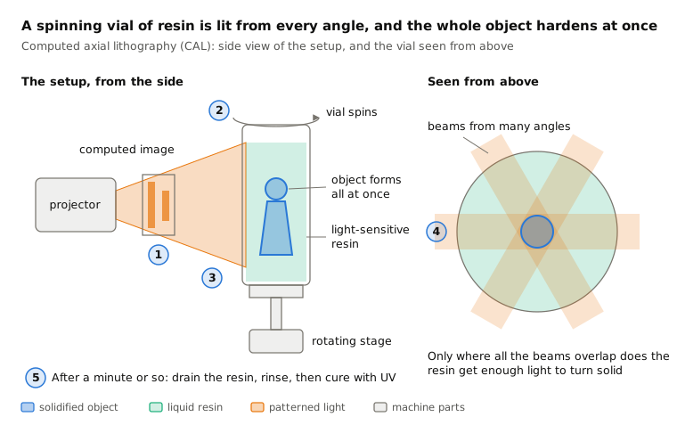
 8.10Volumetric printing (CAL)Light from every angle cures a spinning vial of resin all at once (volumetric printing)Open the lesson
Try it
Put AI to work in your CAD.
Model parts, generate drawings and automate the repetitive work inside your CAD software.